


















Lesson 44 of 45 · Projects and Practice
Cheat sheet: power electronics formulas on one page
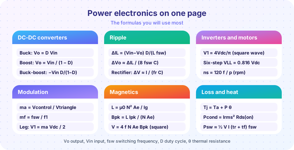
A one-page power electronics cheat sheet: converter ratios, ripple, inverter voltages, modulation, magnetics, thermal and application formulas with typical values and a topology chooser.
When you design a converter, you do not need a hundred equations; you need about thirty, and you need to know when each applies. This page collects them in one place, grouped as the course was, with the typical values that let you sanity-check a result. Print it, keep it next to your keyboard, and when you use a formula for the first time, retrace it in the lesson linked at the end of each group.
What you will learn
- Find the right formula for a converter, inverter, magnetics, thermal or application question.
- Recall typical values (frequencies, flux densities, efficiencies) for sanity checks.
- Choose a topology from three questions.
Key terms
Vin, Vo: input and output voltage; Io: output current; fsw: switching frequency; D: duty cycle.
ΔIL, ΔVo: peak-to-peak inductor current and output voltage ripple.
ma, mf: modulation index and frequency ratio.
θ: thermal resistance in °C/W; Tj, Ta: junction and ambient temperature.
Formulas
Converters and ripple (continuous conduction)
| Quantity | Formula |
|---|---|
| Buck output | Vo = D · Vin |
| Boost output | Vo = Vin / (1 − D) |
| Buck-boost output | Vo = −Vin · D / (1 − D) |
| Buck inductor ripple | ΔIL = (Vin − Vo) · D / (L · fsw) |
| Boost inductor ripple | ΔIL = Vin · D / (L · fsw) |
| Buck output ripple | ΔVo ≈ ΔIL / (8 · fsw · C) + ΔIL · ESR |
| Rectifier ripple | ΔV ≈ I / (fr · C) with fr = 2f for a full-wave rectifier |
| Buck boundary inductance | L = (1 − D) · R / (2 · fsw) |
| Boost input resistance | Rin = (1 − D)² · RL |
Inverters and motors
| Quantity | Formula |
|---|---|
| Full-bridge square wave | V1 = 4·Vdc/π, Vn = V1/n (n odd), THD 48.3 % |
| Phase-shifted bridge | V1 = (4·Vdc/π)·sin(α/2), 3rd harmonic zero at α = 120° |
| Six-step line voltage | vab,rms = 0.816·Vdc, fundamental 0.780·Vdc |
| Synchronous speed | ns = 120·f / p (rpm) |
| Slip, shaft speed | s = (ns − n)/ns, n = (1 − s)·ns |
| V/f control | V/f constant up to base speed; above it torque ∝ 1/f |
| Fan or pump power | P ∝ n³ |
Modulation and control
| Quantity | Formula |
|---|---|
| Modulation index, ratio | ma = V̂ref / V̂car, mf = fsw / f1 |
| Three-phase SPWM | VLL,1 = 0.612·ma·Vdc (linear for ma ≤ 1) |
| Injection or SVPWM | linear to ma = 1.155, VLL,1 = 0.707·Vdc |
| Dead-time error | ΔV ≈ Vdc · td · fsw per leg |
| Buck plant | Gvd = Vin/(1 + sL/R + s²LC), f0 = 1/(2π√LC), Q = R√(C/L) |
| Phase margin | PM = 180° + ∠T(fc); delay costs 180°·fc/fsw |
| Peak current mode | stable if ma > (m2 − m1)/2; safe rule ma ≥ m2/2 |
Magnetics
| Quantity | Formula |
|---|---|
| Gapped inductor | L = µ0·N²·Ae/lg, energy ½LI² |
| Turns, flux density | N = L·Ipk/(Bmax·Ae), Bpk = L·Ipk/(N·Ae) |
| Faraday | v = N·Ae·dB/dt; 4.44·f·N·Ae·Bpk (sine), 4·f·N·Ae·Bpk (square) |
| Area product | Ap ≥ Pin / (2·f·Bpk·J·Ku) |
| Skin depth | δ = √(ρ/(π·f·µ0)), 0.24 mm at 100 kHz (hot copper) |
| Core loss | Pv = k·f^α·B^β |
Loss, heat and applications
| Quantity | Formula |
|---|---|
| Conduction loss | Irms²·Rds(on)(Tj) |
| Switching loss | ½·V·I·(tr + tf)·fsw |
| Junction temperature | Tj = Ta + P·(θJC + θCS + θSA) |
| Heat sink | θSA ≤ (Tj,max − Ta)/P − θJC − θCS |
| Solar fill factor | FF = Pmpp/(Voc·Isc) |
| Power factor | PF = cosφ/√(1 + THDi²) |
| Flyback | Vor = n(Vo + Vf), D = Vor/(Vor + Vin), Lp = Vin·D/(Ip·fsw) |
| Charging time | t = ΔE / (P·η) |
Typical values
| Quantity | Typical value |
|---|---|
| Switching frequency | IGBT drives 2 to 20 kHz; silicon MOSFET DC-DC 100 kHz to 1 MHz; SiC 20 to 200 kHz; GaN 100 kHz to several MHz |
| Ripple current | 20 to 40 % of the load current |
| Dead time | 0.2 to 2 µs |
| Ferrite flux density | about 0.3 T for inductors; 0.05 to 0.2 T peak for 100 kHz transformers |
| Winding current density | 3 to 6 A/mm² with natural cooling |
| Window fill factor | 0.3 to 0.4 |
| Crossover frequency | fsw/10 to fsw/20 for conservative design |
| Phase margin, gain margin | 45° to 60°, at least 6 to 10 dB |
| Junction temperature limit | 125 to 150 °C design, 175 °C or more for SiC |
| Efficiency | converters 92 to 98 %, inverters 97 to 99 %, adapters 90 to 95 % |
Choosing a topology
%%{init: {"theme": "base", "themeVariables": {"primaryColor": "#eef2ff", "primaryBorderColor": "#6366f1", "primaryTextColor": "#1e1b4b", "lineColor": "#6366f1", "fontFamily": "system-ui"}}}%%
flowchart TD
  A("Need isolation from the input?") -->|"yes"| B("Output power?")
  A -->|"no"| C("Output voltage compared with input?")
  B -->|"under about 100 W"| D("Flyback")
  B -->|"100 W to 1 kW"| E("Forward, half-bridge or LLC")
  B -->|"above 1 kW"| F("Full bridge, LLC or dual active bridge")
  C -->|"lower"| G("Buck")
  C -->|"higher"| H("Boost")
  C -->|"either"| I("Buck-boost or SEPIC")
A three-question chooser: isolation, power and voltage ratio decide the topology family.
Common misconceptions
"A cheat sheet replaces understanding." Every formula has conditions: continuous conduction, ideal parts, a particular waveform. Know the conditions or you will misuse the result.
"Typical values are rules." They are starting points; the datasheet and the thermal budget have the last word.
Try it
The first example is a quick calculator for six of the most used formulas. Pick a calculation, enter the numbers, and read the answer.
The second example checks the cheat sheet itself. It tests five formulas numerically against independent calculations: an energy identity, a flux integral, the boost input resistance, the power factor of a distorted current and the six-step line voltage. If a formula were written down wrongly, the comparison would fail.
Press Run (or Ctrl + Enter) to see the result here.
Program input · what you'd type while the program runs
Type the answers before you press Run, one per line. Each time the program reads a line (with input()), it gets the next line from this box.
Check your understanding
Quick check · 5 questions
of 5 answered You scored / 5 · perfect!
-
1. A boost converter has Vin = 5 V and D = 0.75. What is the output voltage?
Vo = Vin / (1 − D) = 5 / 0.25 = 20 V. -
2. Which formula gives the largest fundamental line-line voltage of a three-phase bridge with SVPWM?
SVPWM or third-harmonic injection reaches Vdc/√2 = 0.707 Vdc. -
3. A 6-pole motor runs on 50 Hz. What is the synchronous speed?
ns = 120 × 50 / 6 = 1000 rpm. -
4. Which formula gives the maximum allowed heat-sink resistance?
Rearranging Tj = Ta + P(θJC + θCS + θSA). -
5. A flyback with n = 4, Vo = 15 V and Vf = 0.5 V has a reflected voltage of
Vor = 4 × 15.5 = 62 V.
Summary
- Keep about thirty formulas at hand: converter ratios, ripple, inverter voltages, modulation, magnetics, thermal and application formulas.
- Typical values (frequencies, flux densities, efficiencies, margins) are the quickest sanity check.
- Isolation, power and voltage ratio decide the topology family.
- Always know the conditions under which a formula holds, such as continuous conduction.
Next: Where to go next
Track your progress
Create a free account to tick off lessons and pick up where you left off on any device.
of Power Electronics lessons completed