


















Lesson 14 of 45 · Rectifiers and AC-DC Conversion
Three-Phase and Thyristor Rectifiers
Understand the six-pulse three-phase rectifier, its 1.35 V(LL) output and 6f ripple, and how thyristors with firing angle alpha control the average output voltage.
Factories, data centers and railways are fed with three-phase power. A three-phase rectifier turns it into DC with far less ripple than any single-phase circuit, without needing a big filter, and it draws balanced currents from the grid. Replace its diodes with thyristors and you get something even more useful: a rectifier whose output voltage you can set with a timing signal, with no filter changes, used for big DC motor drives, electrolysis plants, battery chargers and HVDC converters.
What you will learn
- How the six-pulse bridge works and why its ripple is small.
- The formula
Vavg = 1.35 × VLL(rms)and the ripple frequency6f. - How a firing angle
αcontrols the average output of a thyristor rectifier. - What inverter mode means.
Key terms
- Six-pulse bridge: three-phase rectifier with six devices, giving six output pulses per mains cycle.
- Line-to-line voltage (VLL): voltage between two phases,
√3times the phase voltage. - Firing angle (α): delay between the earliest possible turn-on of a thyristor and its actual gate pulse.
- Natural commutation: current handed from one device to the next by the circuit itself.
- Inverter mode: operation of a controlled rectifier with
α > 90°, where it returns power to the AC side.
The six-pulse diode bridge
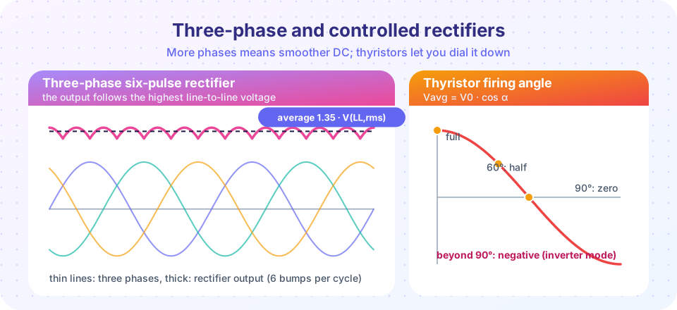
Connect each of the three phases to the middle point of a pair of diodes, one going to the positive output rail and one to the negative rail. At any moment, the diode on the highest phase voltage conducts at the top, and the diode on the lowest phase voltage conducts at the bottom. The output voltage is therefore the difference between the highest and the lowest phase voltages, which equals the highest line-to-line voltage at that moment.
Each line-to-line voltage is the highest for one sixth of the cycle (60°), so the output is a series of six sine segments per cycle. The segment peaks at VLL,pk = √2 × VLL(rms), and the dips between segments are at VLL,pk × cos 30° = 0.866 × VLL,pk.
- Average output:
Vavg = (3/π) × VLL,pk = (3√2/π) × VLL(rms) ≈ 1.35 × VLL(rms) - Ripple frequency:
6f(300 Hz at 50 Hz, 360 Hz at 60 Hz) - Peak-to-peak ripple:
VLL,pk × (1 − 0.866) ≈ 0.134 × VLL,pk, about 14% of the average - Each diode conducts for one third of the cycle (120°).
- Peak inverse voltage of each diode:
VLL,pk.
Example: for a 400 V line-to-line supply, Vavg = 1.35 × 400 = 540 V, which is why the DC bus of a motor drive on a 400 V supply sits near 540 V (a little lower under load). The ripple is at 300 Hz and small, so a modest capacitor, or none for a motor load, is enough.
Why three phases beat one
Compared with a single-phase bridge, the three-phase bridge has a much higher DC output for the same line voltage, six pulses instead of two, one-sixth of the ripple, a smoother current drawn from the grid and no need for a large smoothing capacitor. Its current harmonics are also fewer (the lowest are the 5th and 7th), which are easier to filter.
Thyristors and the firing angle
Replace the diodes with thyristors. A thyristor can only start conducting when two conditions hold: its anode voltage is above the cathode voltage and a gate pulse arrives. A diode bridge starts each device at the natural commutation point, where the incoming phase becomes the highest. With thyristors you can wait for an extra angle α, the firing angle, before sending the pulse.
For a fully controlled three-phase bridge with a smooth (inductive) load current:
Vavg = 1.35 × VLL(rms) × cos α
α = 0°: full output, same as the diode bridge.α = 60°: half of the output.α = 90°: average zero. The positive and negative parts cancel.α > 90°: the average becomes negative. With a load that can supply energy (a DC machine braking, or a battery) power flows from the DC side back to the AC grid: the converter acts as a line-commutated inverter. It is used in HVDC links and in regenerative drives. (Firing too close to 180° risks commutation failure, so a safe margin is kept.)
The price of delayed firing is a lower power factor on the AC side: the fundamental current lags the voltage by about α, so the displacement power factor is about cos α. Using thyristors at large α draws a lot of reactive power.
A single-phase example for comparison
For a single-phase fully controlled bridge with a resistive load, the thyristors conduct from α to 180° in each half-cycle, and the average output is
Vavg = (Vpk / π) × (1 + cos α)
For 230 V rms mains, Vpk = 325 V: α = 0° gives 207 V; α = 60° gives 155 V; α = 90° gives 104 V; and α = 180° gives 0 V. This is the idea behind a phase-controlled light dimmer using a TRIAC, which is a two-direction thyristor.
Common misconceptions
- "The three-phase rectifier output is three times the single-phase output." It depends on how you compare. With line-to-line voltage
VLL, the six-pulse bridge gives1.35 VLL, while a single-phase bridge on the sameVLLgives0.9 VLL. - "A thyristor rectifier at
α = 90°consumes no power." The average output voltage is zero, but the converter still draws reactive power from the supply, and the current in the thyristors flows in pulses.
Try it
First, the program below builds the three-phase waveforms from their definitions and applies a firing delay. It plots the output for α = 0°, 30°, 60° and 90°, and compares each average with the formula. The simulation assumes continuous load current (a large inductance) and ideal devices.
Press Run (or Ctrl + Enter) to see the result here.
Program input · what you'd type while the program runs
Type the answers before you press Run, one per line. Each time the program reads a line (with input()), it gets the next line from this box.
Second, a single-phase controlled rectifier with a resistive load. The code applies the firing delay to a rectified 230 V rms sine and compares the numerical average with (Vpk/π)(1 + cos α).
Press Run (or Ctrl + Enter) to see the result here.
Program input · what you'd type while the program runs
Type the answers before you press Run, one per line. Each time the program reads a line (with input()), it gets the next line from this box.
Check your understanding
Quick check · 5 questions
of 5 answered You scored / 5 · perfect!
-
1. A six-pulse diode bridge is fed from a 400 V line-to-line supply. What is the ideal average DC output?
Vavg = 1.35 × 400 V ≈ 540 V. -
2. What is the ripple frequency of a six-pulse rectifier on 50 Hz mains?
Six pulses per cycle at 50 Hz gives 6 × 50 = 300 Hz. -
3. A fully controlled three-phase bridge fires at α = 60°. By what factor is the average output reduced compared with α = 0°?
The output scales with cos α, and cos 60° = 0.5. -
4. What does a negative average output at α > 90° mean for a line-commutated converter?
With a load that can supply energy, power flows from the DC side to the AC grid. -
5. A single-phase resistive-load controlled rectifier on 230 V rms (Vpk = 325 V) fires at α = 90°. What is the average output?
(325/π)(1 + cos 90°) = 103.5 V ≈ 104 V.
Summary
- The six-pulse bridge outputs the highest line-to-line voltage:
Vavg = 1.35 VLL, ripple at6f, about 14% peak-to-peak. - Each diode conducts 120° per cycle and blocks
VLL,pk. - With thyristors,
Vavg = 1.35 VLL cos α(continuous current);α > 90°gives inverter mode. - Phase control costs power factor (about
cos α). - Single-phase resistive-load phase control:
Vavg = (Vpk/π)(1 + cos α).
Track your progress
Create a free account to tick off lessons and pick up where you left off on any device.
of Power Electronics lessons completed