


















Lesson 16 of 45 · DC-DC Converters
Chapter 4 Overview: DC-DC Converters
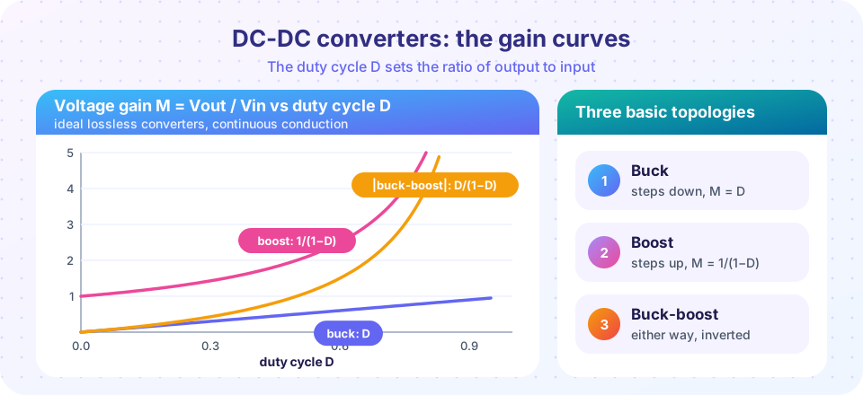
Overview of DC-DC converters: buck, boost and buck-boost topologies, the voltage-gain curves versus duty cycle, continuous and discontinuous conduction and how to pick one.
Your phone battery gives 3.7 V, yet the screen, processor and radio all need different voltages. A car gives 12 V while a USB port wants 5 V. A solar panel varies from 15 V to 40 V depending on the sun, but the inverter's DC bus needs a steady 400 V. Every one of these jobs is done by a DC-DC converter, and the three basic circuits in this chapter, the buck, the boost and the buck-boost, are the building blocks of nearly all of them.
What you will learn
- What each of the three basic converters does and which gain curve it follows.
- Why all three use a switch, a diode (or second switch), an inductor and a capacitor.
- What continuous and discontinuous conduction mean.
- How to pick a topology from the input and output voltages.
Key terms
- Buck converter: steps voltage down,
Vout = D × Vin. - Boost converter: steps voltage up,
Vout = Vin / (1 − D). - Buck-boost converter: inverts and steps up or down,
Vout = −Vin × D / (1 − D). - CCM and DCM: continuous and discontinuous conduction mode, whether inductor current stays above zero all the time.
- Volt-second balance: in steady state, the average voltage across an inductor over one cycle is zero.
Three basic circuits
The shared parts
One rule explains all
One rule that derives all three gains
In steady state, the inductor current at the end of a cycle equals its value at the start. Since v = L di/dt, the average voltage across the inductor over a cycle must be zero. This is volt-second balance: the area of the positive voltage pulses equals the area of the negative pulses.
Take the buck converter. While the switch is on (time D T), the inductor sees Vin − Vout. While it is off (time (1 − D) T), it sees −Vout. Balance:
(Vin − Vout) × D T = Vout × (1 − D) T, which gives Vout = D × Vin.
The same method gives Vout = Vin / (1 − D) for the boost and Vout = −Vin D / (1 − D) for the buck-boost. You will do each derivation in the coming lessons.
Choosing a topology
| Need | Input and output | Choose |
|---|---|---|
| 12 V to 5 V | output always below input | Buck |
| 5 V to 12 V | output always above input | Boost |
| Battery from 3 V to 4.2 V to a 3.3 V rail | output within the input range | Buck-boost (or SEPIC, or a buck-boost with four switches) |
| Need a negative rail from a positive input | inverted output | Inverting buck-boost |
Real designs often use the same switch and inductor in a more elaborate form: synchronous versions replace the diode with a second MOSFET, isolated versions (flyback, forward, LLC) add a transformer, and multiphase versions interleave several in parallel for high currents like those used for CPUs.
Continuous and discontinuous conduction
If the load is heavy enough, the inductor current never reaches zero during the cycle: continuous conduction mode (CCM). The gain formulas above hold exactly for CCM and depend only on D. At light load, the inductor current can fall to zero before the cycle ends and stay there for a while: discontinuous conduction mode (DCM). In DCM the gain depends on the load as well as D, and the control loop behaves differently. Designers choose the inductor so that the converter stays in CCM at rated load, and accept DCM at light load or design for it.
What each lesson covers
- The buck converter: derivation, ripple, inductor and capacitor sizing, CCM versus DCM, and a time-domain simulation.
- The boost converter: derivation, the input-inductor advantage, and the right-half-plane zero.
- The buck-boost converter: inversion, gain, and related topologies.
- Chapter 4 review: design equations and a ten-question quiz.
Common misconceptions
- "A boost converter can produce any voltage if D is close to 1." The ideal gain
1/(1 − D)goes to infinity, but real losses (resistance in the inductor and switch) pull the gain down and efficiency collapses above roughlyD = 0.8to0.9. - "The inductor stores energy forever." It stores energy only during part of each cycle and passes it to the output; the average stored energy is constant in steady state.
Try it
The first demo plots the three gain curves and a small design helper that gives the ideal duty cycle for a spec. It uses the ideal CCM formulas, with no losses.
Press Run (or Ctrl + Enter) to see the result here.
Program input · what you'd type while the program runs
Type the answers before you press Run, one per line. Each time the program reads a line (with input()), it gets the next line from this box.
Check your understanding
Quick check · 4 questions
of 4 answered You scored / 4 · perfect!
-
1. Which converter can only produce an output equal to or below the input voltage?
The buck gain is D, which is at most 1. -
2. What does volt-second balance say?
Otherwise the inductor current would keep growing or shrinking every cycle. -
3. A boost converter has D = 0.75 and Vin = 5 V. Ideal Vout?
Vout = Vin / (1 − D) = 5 / 0.25 = 20 V. -
4. What defines discontinuous conduction mode?
At light load the current reaches zero before the cycle ends.
Summary
- Buck:
Vout = D Vin; boost:Vout = Vin/(1 − D); buck-boost:Vout = −Vin D/(1 − D). - Volt-second balance on the inductor derives all three gains.
- CCM follows the simple formulas; DCM makes gain load-dependent.
- Choose the topology from the relation between input and output voltages.
Next: The Buck Converter
Track your progress
Create a free account to tick off lessons and pick up where you left off on any device.
of Power Electronics lessons completed