


















Lesson 30 of 45 · Control and Modulation
Chapter 6 review: control and modulation
Review PWM, modulation index, harmonics, small-signal models, phase margin and current-mode control with a recap table, a loop-design helper and a ten-question quiz.
This chapter gave you the two tools that turn a circuit of switches into a controlled converter: modulation decides when each switch turns on and off, and feedback decides how much. You learned to describe PWM with two numbers, ma and mf, to model a buck converter as a second-order filter, to read a Bode plot for stability, and to use an inner current loop to simplify the design. The review below collects the key results and then asks you to use them together.
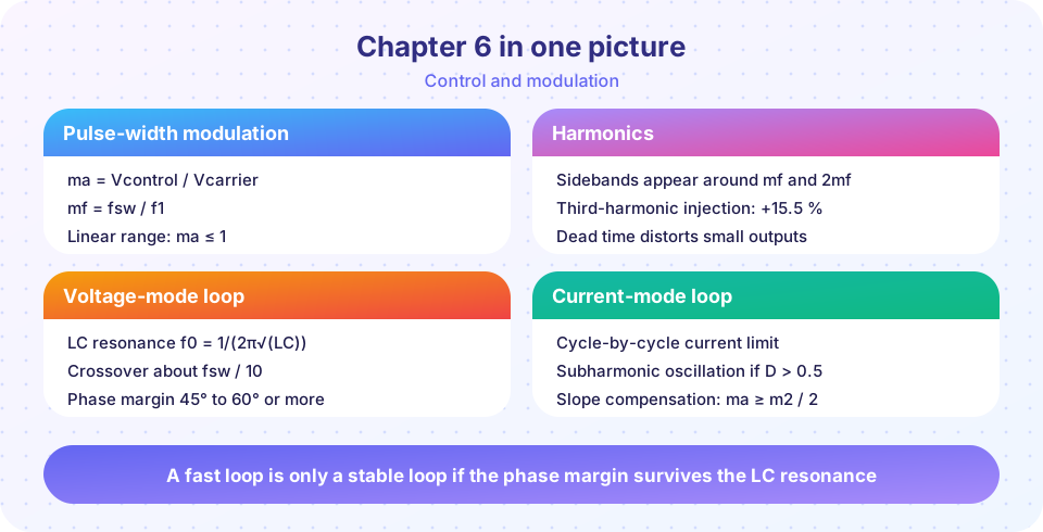
Recap table
| Topic | Key result | Lesson |
|---|---|---|
| PWM generation | compare a reference with a carrier; d = vc / Vramp |
PWM and SPWM |
| Modulation index | ma = V̂ref / V̂car, linear for ma ≤ 1 |
same |
| Frequency ratio | mf = fsw / f1; harmonics in clusters around mf, 2mf, … |
same |
| Three-phase SPWM output | VLL,1 = 0.612 · ma · Vdc |
same |
| Third-harmonic injection | linear range to ma = 1.155, VLL,1 = 0.707 Vdc |
same |
| Dead-time error | ΔV ≈ Vdc · td · fsw per leg |
same |
| Buck plant | Gvd = Vin / (1 + sL/R + s²LC), f0 = 1/(2π√LC), Q = R√(C/L) |
Voltage-mode control |
| Stability | phase margin 45° to 60°, gain margin 6 to 10 dB | same |
| Delay | costs 360° · fc · Td, with Td ≈ Ts/2 |
same |
| Type III compensator | integrator, two zeros near f0, two poles high |
same |
| Peak current mode | plant ≈ R/(1 + sRC); cycle-by-cycle limit |
Current-mode control |
| Subharmonic oscillation | D > 0.5: error factor −D/(1−D); fix with ma ≥ m2/2 |
same |
A worked loop design
Design the loop of a 12 V to 5 V buck with L = 22 µH, C = 100 µF, R = 2 Ω and fsw = 200 kHz.
- Plant.
f0 = 1/(2π√(22e-6 × 100e-6)) = 3.39 kHz,Q = 2 × √(100/22) = 4.26. The plant phase near 20 kHz is almost −180°. - Crossover. Choose
fc = fsw/10 = 20 kHz. - Zeros. Two zeros at about
0.5 f0 = 1.7 kHzeach add nearly +85° at crossover. - Poles. Two poles at
0.75 fsw = 150 kHzeach take away about 8°. - Delay.
Td = Ts/2 = 2.5 µscosts360 × 20,000 × 2.5e-6 = 18°. - Margin.
PM ≈ 180° − 177.7° + (−90° + 170° − 15°) − 18° = 49°, good.
The helper below repeats this arithmetic for any converter and crossover.
Try it
The first example is a loop-design helper. It computes the plant resonance and the phase margin from the plant phase, the compensator phase and the delay, and sweeps the crossover frequency to show where the margin collapses. It uses the same formulas as the lessons.
Press Run (or Ctrl + Enter) to see the result here.
Program input · what you'd type while the program runs
Type the answers before you press Run, one per line. Each time the program reads a line (with input()), it gets the next line from this box.
The second example converts a wanted three-phase line voltage into the modulation index for sinusoidal PWM and for SVPWM, and warns when the DC link is too small. It applies VLL,1 = 0.612 · ma · Vdc and VLL,1,max = 0.707 · Vdc.
Check your understanding
Quick check · 10 questions
of 10 answered You scored / 10 · perfect!
-
1. A triangle carrier has an amplitude of 5 V and the sine reference has an amplitude of 4 V. What is ma?
ma = 4 / 5 = 0.8. -
2. A 60 Hz inverter uses a 9 kHz carrier. What is mf?
mf = 9000 / 60 = 150. -
3. A three-phase SPWM inverter has Vdc = 400 V and ma = 1. What is the fundamental line-line rms voltage?
0.612 × 400 = 245 V. -
4. What is the maximum fundamental line-line rms with SVPWM for Vdc = 400 V?
0.707 × 400 = 283 V. -
5. Which statement about dead time is true?
During dead time the current flows through a diode, so the output follows the current direction. -
6. A buck has L = 33 µH and C = 220 µF. Approximately what is the LC resonance?
√(33e-6 × 220e-6) = 8.52e-5, so f0 = 1/(2π × 8.52e-5) = 1.87 kHz. -
7. A loop crosses 0 dB at 30 kHz with a plant+compensator phase of −140°. What is the phase margin?
PM = 180° + (−140°) = 40°. -
8. What does a half-period delay cost at crossover fc with switching period Ts?
360° × fc × (Ts/2) = 180° × fc / fsw. -
9. A peak-current-mode buck runs at D = 0.6. What happens without slope compensation?
For D > 0.5 the error factor D/(1−D) = 1.5 exceeds one. -
10. What is the 'safe rule' for the compensating ramp?
That guarantees stability for every duty cycle.
Summary
- PWM:
d = vc/Vramp;masets the amplitude,mfplaces the harmonics; three-phase SPWM gives0.612·ma·Vdcand SVPWM reaches0.707 Vdc. - A buck's plant is a second-order low-pass
Vin/(1 + sL/R + s²LC); the loop needs 45° to 60° of phase margin and delay reduces it. - Peak current-mode control gives a first-order plant and a cycle-by-cycle limit, but needs a ramp
ma ≥ m2/2above 50 % duty. - Next, the physical limits: the magnetic parts that store and move energy, and the heat that every loss creates.
Track your progress
Create a free account to tick off lessons and pick up where you left off on any device.
of Power Electronics lessons completed