


















Lesson 29 of 45 · Control and Modulation
Current-mode control
Learn peak current-mode control of switching converters: the inner current loop, cycle-by-cycle current limit, subharmonic oscillation above 50 percent duty and slope compensation.
Voltage-mode control watches only the output voltage. Its plant has the awkward LC double pole, so the compensator needs a lot of phase boost, and nothing in the loop knows about the inductor current until it is too late: a short circuit can drive the inductor into saturation within a few cycles. Current-mode control fixes both problems by adding a second, inner loop that measures the inductor current directly.
This lesson explains how peak current-mode control works, why it makes the plant first-order and the compensator simpler, and why it needs one odd-looking trick, slope compensation, to remain stable when the duty cycle exceeds 50 %.
What you will learn
- Describe the two loops of peak current-mode control and what each does.
- Explain why the plant becomes a single pole and which compensator suits it.
- Derive the condition for subharmonic oscillation and the slope-compensation rule.
- Use cycle-by-cycle limiting to protect a converter at start-up and in overload.
- Compute the required compensating ramp for a given converter.
Key terms
Peak current-mode control: the switch turns on at each clock edge and off when the inductor current reaches a threshold set by the error amplifier.
Inner loop: the fast current loop; the outer loop is the voltage loop.
Subharmonic oscillation: an instability at half the switching frequency, in which the duty cycle alternates between wide and narrow pulses.
Slope compensation: a ramp subtracted from the current threshold (or added to the sensed current) to stabilize the inner loop.
Leading-edge blanking: ignoring the current-sense signal for a short time after turn-on to avoid false trips from switching spikes.
How the two loops work
In peak current-mode control the controller has a clock at the switching frequency. At every clock edge the switch turns on and the inductor current rises with slope m1 = (Vin − Vo)/L (for a buck). The sensed current is compared with a threshold Ic supplied by the voltage error amplifier. When the current reaches the threshold the switch turns off, and the current falls with slope −m2 = −Vo/L until the next clock edge.
The two loops therefore work like this:
- Inner loop (fast). It forces the peak inductor current to equal
Ic. From the point of view of the outer loop, the inductor has become a controlled current source. - Outer loop (slow). An error amplifier compares the output voltage with the reference and sets
Ic. If the output is too low, it asks for more current.
Because the inductor current no longer depends on the output voltage through the LC resonance, the outer loop sees only the capacitor and load:
Gvc(s) = vo / Ic ≈ R / (1 + s · R · C)
(an approximation valid well below fsw/2). The plant has a single pole at 1/(2πRC) instead of a resonant double pole, the phase never drops below −90° and a type II compensator (an integrator plus one zero, often with a high-frequency pole) gives a comfortable phase margin without elaborate tuning. Near fsw/2 there remains a small sampled-data double pole that you must keep above crossover.
Advantages
- Cycle-by-cycle current limit. The threshold
Iccan be clamped, so no cycle can exceed the limit. This protects against short circuits and gives a controlled start-up. - Built-in input-voltage feed-forward. A change in
Vinchanges the inductor slope immediately, and the inner loop corrects it within the same cycle. - Easy paralleling. Converters that share the same
Icshare current naturally. - Simple, stable compensation. A first-order plant is forgiving.
Disadvantages
- Noise on the sensed current can end the pulse early (jitter); leading-edge blanking and a filter help.
- Sub-harmonic oscillation above 50 % duty, discussed next.
- More parts: a current-sense element and a ramp generator.
Why duty above 50 % is a problem
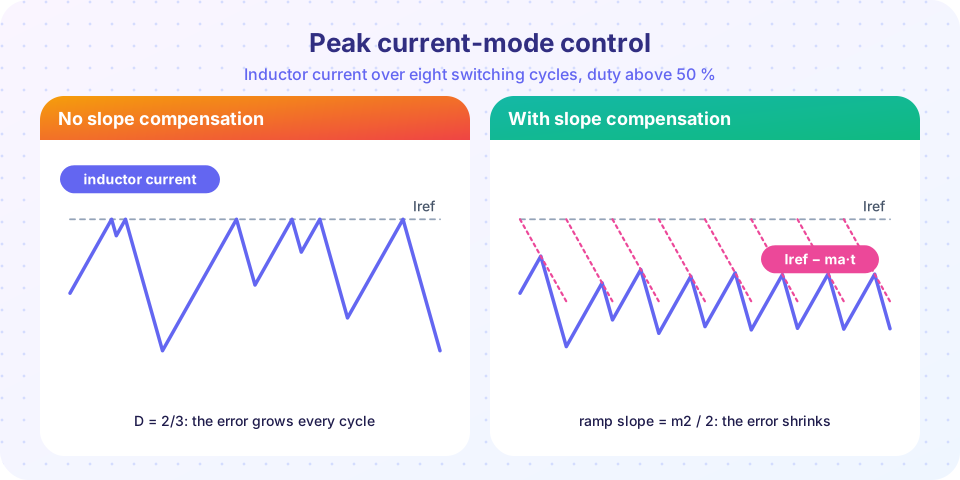
Suppose the valley current at the start of a cycle is lower than nominal by Δ0. Because the peak is pinned at Ic, the current must climb for longer, by Δ0/m1, so the on-time grows. That shortens the off-time by the same amount, the current has less time to fall, and the next valley is higher than nominal by m2·Δ0/m1. The disturbance has changed sign and been multiplied by m2/m1:
Δ1 = − (m2 / m1) · Δ0 (no compensation)
with m2/m1 = D/(1 − D). For D < 0.5 this ratio is below one and the error shrinks; for D > 0.5 it exceeds one, and the error alternates in sign and grows: the converter settles into a period-two limit cycle at fsw/2. That is exactly what the left plot of the figure shows.
Slope compensation
Subtract a ramp of slope ma from the threshold, so the comparator trips at Ic − ma·t where t is the time since the clock. A longer on-time then meets a lower threshold, which reduces the disturbance:
Δ1 = − (m2 − ma) / (m1 + ma) · Δ0
The error decays if |m2 − ma| < m1 + ma, i.e. if
ma > (m2 − m1) / 2
Since m2 − m1 < m2, the choice ma ≥ m2 / 2 guarantees stability for every duty cycle, and ma = m2 makes Δ1 = 0: the error disappears in one cycle (deadbeat), though the current loop then behaves more like voltage mode. A common practical value is ma = 0.5 m2 to ma = m2.
Worked example. A buck converter: Vin = 12 V, Vo = 8 V, L = 10 µH, fsw = 500 kHz. Then D = 0.667, m1 = 4 V / 10 µH = 0.4 A/µs, m2 = 8 V / 10 µH = 0.8 A/µs. The condition ma > 0.2 A/µs is the minimum; the rule ma ≥ 0.4 A/µs is safe. With a 0.1 Ω sense resistor, 0.4 A/µs equals 40 mV/µs, so the ramp must add 80 mV across the 2 µs period. The cost of slope compensation is that the current limit now droops with duty cycle, because the ramp has risen further by the time the switch turns off.
Peak current-mode ICs usually include a ramp generator and an adjustable slope compensation. If you design with discrete parts, choose the ramp for the worst case: the largest m2, which occurs at the highest output voltage and the smallest inductance.
Common misconceptions
"Current-mode control limits the output current." It limits the peak inductor current in each cycle. The average load current can still be a little lower or higher, and a regulated output also needs the outer loop.
"Slope compensation is only for noisy circuits." It is a stability requirement for duty cycles above 50 %, whatever the noise.
"The current loop makes the voltage loop unnecessary." The inner loop only controls current. Without the voltage loop, the output would drift with load.
Try it
The first example iterates the exact cycle-by-cycle map of the inductor current for a duty cycle of two thirds (m1 = 1, m2 = 2, arbitrary units) for four values of ma and plots the valley current. It confirms the stability condition derived above.
Press Run (or Ctrl + Enter) to see the result here.
Program input · what you'd type while the program runs
Type the answers before you press Run, one per line. Each time the program reads a line (with input()), it gets the next line from this box.
The second example is a cycle-by-cycle simulation of a 12 V to 5 V buck with peak current-mode control, an outer PI voltage loop, a 6 A current limit and a load step. It integrates the circuit with small time steps and shows the controlled start-up. It is a simplified model with an ideal switch, an ideal diode and ideal current sensing.
Press Run (or Ctrl + Enter) to see the result here.
Program input · what you'd type while the program runs
Type the answers before you press Run, one per line. Each time the program reads a line (with input()), it gets the next line from this box.
The third example is a slope-compensation calculator. Enter the converter's input and output voltages and inductance and choose how much compensation you add; it reports the slopes, the minimum ramp and whether the inner loop is stable. It applies the formulas from this lesson.
Check your understanding
Quick check · 5 questions
of 5 answered You scored / 5 · perfect!
-
1. What does the inner loop of peak current-mode control regulate?
The switch turns off when the inductor current reaches the threshold set by the outer loop. -
2. Why does peak current-mode control make the compensator simpler?
A first-order plant never loses more than 90° of phase. -
3. For which duty cycles does uncompensated peak current mode oscillate at half the switching frequency?
The error factor is D/(1−D), which exceeds 1 for D > 0.5. -
4. A buck has Vo = 5 V and L = 5 µH. What compensating ramp slope is the 'safe rule' m2/2?
m2 = Vo/L = 5 / 5 = 1 A/µs; half of it is 0.5 A/µs. -
5. What is a main benefit of cycle-by-cycle current limiting?
Clamping the threshold Ic caps the peak current in every cycle.
Summary
- Peak current-mode control has a fast inner loop that sets the peak inductor current and a slow outer voltage loop that sets the threshold.
- The plant becomes first-order (
≈ R / (1 + sRC)), so a type II compensator is enough, and the current is limited cycle by cycle. - Above 50 % duty the inner loop oscillates at
fsw/2unless a rampma > (m2 − m1)/2is added; the safe rule isma ≥ m2/2. - The price is a current-sense element, noise sensitivity and a current limit that varies slightly with duty.
Next: Chapter 6 review
Track your progress
Create a free account to tick off lessons and pick up where you left off on any device.
of Power Electronics lessons completed