


















Lesson 3 of 45 · Getting Started
Efficiency and the Loss Budget
Calculate converter efficiency, split losses into conduction, switching, magnetic and gate-drive parts, and see how heat and frequency shape every design.
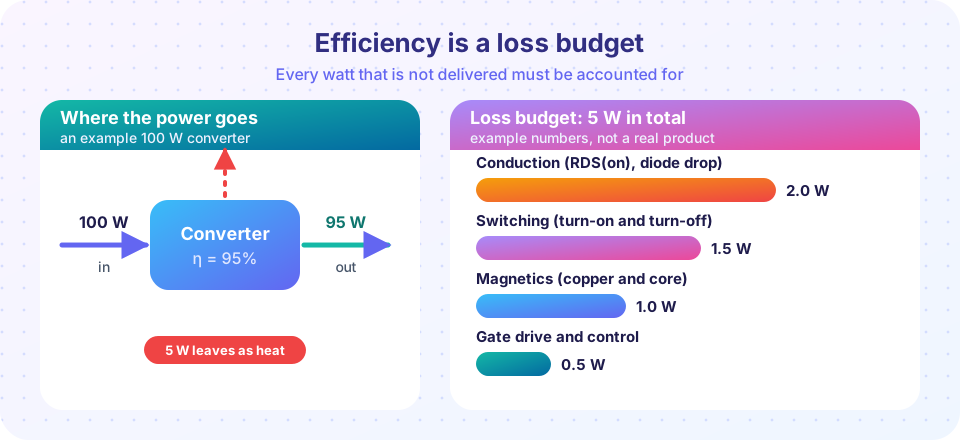
Every power electronics designer keeps a running tally of one number: the efficiency. If a converter takes 100 W in and delivers 95 W, it is 95% efficient, and 5 W has become heat. That sounds small, but the heat decides the size of heat sinks, the temperature of components, the lifetime of the product and, in a solar plant or a data center, a large electricity bill.
What you will learn
- How to compute efficiency and heat from input and output power.
- The four main loss groups in a switching converter.
- How to estimate conduction, switching and gate-drive loss with simple formulas.
- Why the loss budget changes with frequency and load.
Key terms
- Efficiency (η):
η = Pout / Pin, expressed as a fraction or a percentage. - Conduction loss: power lost because current flows through a resistance or voltage drop.
- Switching loss: energy lost during each on-to-off or off-to-on transition.
- Gate-drive loss: energy needed to charge and discharge the transistor's gate.
- Loss budget: a list of every loss with its value in watts.
Efficiency and heat
Efficiency is the ratio of output to input power:
η = Pout / Pin, and Ploss = Pin − Pout = Pout × (1/η − 1).
A converter that delivers 100 W at 95% efficiency draws 100 / 0.95 = 105.3 W and wastes 5.3 W. At 90% efficiency the waste doubles to 11.1 W. Look at the numbers carefully: going from 95% to 97% efficiency does not feel like much, but it cuts the loss from 5.3 W to 3.1 W, which is a reduction of about 41%. This is why designers fight for the last few percent.
The four loss groups
Conduction loss
Whenever a switch is on, current flows through its on-resistance. For a MOSFET with RDS(on) = 5 mΩ carrying an rms current of 10 A:
Pcond = I² × R = 10² × 0.005 = 0.5 W.
For a diode with a forward drop VF = 0.5 V carrying an average current of 4 A, Pcond ≈ VF × I = 2 W. Notice that the diode, with its nearly constant voltage drop, usually loses more than the MOSFET, which is why modern converters replace diodes with MOSFETs (called synchronous rectification).
Switching loss
During a transition, voltage and current overlap for a short time. A good first estimate for a hard-switched transistor is
Psw ≈ ½ × V × I × (tr + tf) × fsw
where tr and tf are the rise and fall times. With 48 V, 10 A, tr = tf = 20 ns and fsw = 200 kHz: Psw = 0.5 × 48 × 10 × 40 ns × 200 kHz = 1.92 W. This is proportional to frequency, which is why the switching frequency is such an important knob.
Gate-drive loss
The gate is a capacitor. Charging and discharging it each cycle costs Pgate = Qg × Vgs × fsw. With Qg = 60 nC, Vgs = 10 V, fsw = 200 kHz: Pgate = 60 nC × 10 V × 200 kHz = 0.12 W. It is small here, but becomes important for big transistors at high frequency.
Magnetic and other losses
Inductors lose power in their copper winding (I² × RDC, plus extra at high frequency) and in their core (the magnetic material heats under alternating flux). Capacitors have a small equivalent series resistance (ESR), and the PCB traces have resistance too. Chapter 7 treats these in depth.
A worked loss budget
Take the example converter from the picture: 100 W out, 5 W of loss.
| Loss | Watts | Share |
|---|---|---|
| Conduction (MOSFET and diode) | 2.0 | 40% |
| Switching | 1.5 | 30% |
| Magnetics (copper and core) | 1.0 | 20% |
| Gate drive and control | 0.5 | 10% |
| Total | 5.0 | 100% |
In the picture the converter takes in 100 W and delivers 95 W, so η = 95%. If 100 W were the output instead, the efficiency would be 100 / 105 = 95.2%. Always state which power you divide by. A designer reading this table knows where to work: halving switching loss by lowering the frequency saves 0.75 W, but may require a bigger inductor and raise magnetic loss. That is the trade-off.
Efficiency changes with load
Fixed losses (control circuits, gate drive, core loss) do not shrink when the load drops, so at light load efficiency falls. At heavy load, I²R losses grow with the square of current and efficiency falls again. The curve of efficiency against load current is usually a hump, with the best efficiency at 30% to 60% of rated load.
Common misconceptions
- "Efficiency is a fixed property of a converter." It depends on load, input voltage, switching frequency and temperature. A datasheet number is for specific conditions.
- "98% and 99% are almost the same." In terms of heat they differ by a factor of two: 2% loss versus 1% loss.
Try it
Plot how total loss and efficiency change with switching frequency for the example MOSFET stage. The conduction loss is constant, switching and gate loss grow with frequency. This is a model built from the formulas above with fixed example parameters.
Press Run (or Ctrl + Enter) to see the result here.
Program input · what you'd type while the program runs
Type the answers before you press Run, one per line. Each time the program reads a line (with input()), it gets the next line from this box.
Press Run (or Ctrl + Enter) to see the console output here.
No output.
The calculator makes the point from the beginning of the lesson: every extra percent near the top halves the heat again and again.
Check your understanding
Quick check · 4 questions
of 4 answered You scored / 4 · perfect!
-
1. A converter delivers 200 W and draws 215 W. What is its efficiency?
η = 200 / 215 ≈ 0.930, or 93%. The loss is 15 W. -
2. Which loss is proportional to the switching frequency?
Each transition costs a fixed energy, so the average power is energy per transition times the number of transitions per second. -
3. A MOSFET with RDS(on) = 8 mΩ carries 12 A rms. How much is the conduction loss?
P = I² × R = 144 × 0.008 = 1.152 W. -
4. Why does efficiency usually fall at very light load?
Gate drive, control and core losses do not shrink with load, so they dominate when the output power is small.
Summary
η = Pout / PinandPloss = Pout × (1/η − 1).- Losses divide into conduction, switching, gate-drive and magnetic/other.
Pcond = I² × RDS(on),Psw ≈ ½ V I (tr + tf) fsw,Pgate = Qg × Vgs × fsw.- Near the top, each percent of efficiency matters: 98% means half the heat of 96%.
- Efficiency depends on load, voltage, frequency and temperature.
Track your progress
Create a free account to tick off lessons and pick up where you left off on any device.
of Power Electronics lessons completed