


















Lesson 24 of 45 · Inverters and Motor Drives
Motor drives and V/f control
Learn how a variable-frequency drive runs an induction motor: synchronous speed, slip, constant V/f, low-speed boost, field weakening, DC-link sizing and braking.
Roughly half of all electricity used in the world is consumed by electric motors, and most of those motors run at a fixed speed fixed by the mains frequency. Throttling a fan with a damper or a pump with a valve wastes a large part of that energy. A variable-frequency drive (VFD) removes the waste: it feeds the motor a voltage whose frequency matches the wanted speed, so the motor itself does only the work needed.
This lesson connects the three-phase inverter to the machine it drives. You need no deep motor theory, only a few facts about the induction motor and one rule, constant volts per hertz, that explains how drives behave from standstill to full speed.
What you will learn
- Calculate synchronous speed and slip of an induction motor.
- Explain why the drive keeps voltage proportional to frequency.
- Describe low-speed boost, the constant-torque region and field weakening.
- Check whether a DC link can supply the voltage a motor needs.
- Name the main parts of a drive and how braking energy is handled.
Key terms
Synchronous speed (ns): the speed of the rotating magnetic field, ns = 120·f / p in rpm for p poles.
Slip (s): the relative difference between field speed and rotor speed, s = (ns − n) / ns.
V/f control: a scalar control method that keeps the voltage-to-frequency ratio constant.
Base speed (base frequency): the speed at which the drive reaches rated voltage.
Field weakening: operating above base speed with constant voltage, so the flux falls as 1/f.
Speed, slip and flux
The stator windings of a three-phase motor create a magnetic field that rotates at the synchronous speed
ns = 120 · f / p (rpm, p = number of poles)
A 4-pole motor on 50 Hz has ns = 120 × 50 / 4 = 1500 rpm; on 60 Hz it is 1800 rpm. An induction motor always runs a little slower: the rotor must "slip" relative to the field so that currents are induced in it. With slip s, the rotor speed is n = (1 − s)·ns. A typical motor at full load slips by 2 to 6 %, so a 4-pole 50 Hz machine turns at about 1440 to 1470 rpm.
To change speed, change f. But frequency is not the only quantity that matters. Faraday's law, which you will meet again in the magnetics chapter, says the flux in the stator iron is
Φ ≈ V / (4.44 · f · N) (sine wave, N turns)
If you halve the frequency and keep the voltage, the flux doubles. The iron saturates, the magnetizing current explodes, and the motor overheats. If you halve the voltage but keep the frequency, the flux halves and so does the available torque. The cure is to change both together so that V/f stays constant, and with it the flux and the torque capability.
The V/f profile
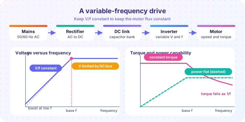
A typical European motor is rated for 400 V line-to-line at 50 Hz: that is 8 V/Hz. A drive running it at 25 Hz supplies about 200 V, at 10 Hz about 80 V. This gives three regions:
- Low-speed boost. At low frequency the voltage is small and the resistive drop in the stator winding (
I·R1) is a large share of it. The flux falls and so does the torque. Drives add a boost, typically a few percent of rated voltage at 0 Hz, to compensate. Too much boost saturates the motor at light load. - Constant-torque region (up to base frequency). With constant flux the motor can deliver rated torque at any speed. Mechanical power grows in proportion to speed.
- Field weakening (above base frequency). The inverter cannot raise the voltage beyond the DC link, so
Vstays constant whilefincreases: flux falls as1/f, available torque falls as1/fand power stays about constant. At very high speed the motor's breakdown torque, which falls as1/f², becomes the limit.
Can the DC link supply enough voltage?
The DC link of a drive on 400 V mains is about 400 × √2 = 566 V (the rectified peak, less a little for load). The largest fundamental line-to-line rms voltage a two-level bridge can make with sinusoidal PWM is Vdc/(2√2)·√3 = 0.612·Vdc, which is only 346 V here. Space-vector modulation (Chapter 6) reaches Vdc/√2 = 0.707·Vdc, which is 400 V. The mains-fed 400 V drive therefore just reaches the motor's rated voltage at no load (under load the link sags to about 540 V, which gives roughly 95 %), so there is no voltage margin above the base frequency; that is why base frequency is usually the rated frequency of the motor.
The parts of a drive
A general-purpose VFD has five blocks:
- Rectifier: a diode bridge for a plain drive; an active front end if energy must return to the grid.
- DC link: electrolytic or film capacitors that hold the voltage steady. They also absorb the inverter's ripple current. A soft-start resistor limits the inrush current at power-up.
- Inverter: six IGBTs (or MOSFETs) with gate drivers, usually modulated at 2 to 16 kHz.
- Brake chopper and resistor (optional): when the motor slows, it works as a generator and pumps energy into the DC link, raising its voltage. A diode rectifier cannot return the energy to the mains, so the chopper switches a resistor across the link when the voltage exceeds a limit.
- Controller: scalar V/f control as described here, or vector control (field-oriented control) that treats the motor current as two components, one for flux and one for torque, and gives much better dynamic performance. Both use the same inverter hardware.
For fans and pumps, torque falls with the square of speed, so power falls with the cube of speed. A fan at 80 % speed needs only 51 % of the power. This is the largest source of energy savings from variable-speed drives.
Common misconceptions
"I can run a 50 Hz motor at 100 Hz by doubling the voltage." Voltage cannot exceed the rated insulation level and the DC link. Above base frequency voltage stays constant and the torque falls.
"Reducing frequency alone slows the motor without harm." At constant voltage the flux rises as 1/f, saturating the iron and overheating the motor.
"A drive can always brake a motor." Without a brake resistor or a regenerative front end the DC link voltage rises and the drive trips on overvoltage.
"A motor at low speed is cooled as well as at full speed." A shaft-mounted fan turns slower, so the motor may need derating or forced cooling at low speed and high torque.
Try it
The first example builds the V/f profile of a 400 V, 50 Hz motor with 5 % boost, field weakening up to 100 Hz, and the resulting torque and power capability. It is a model of the idealized control law.
Press Run (or Ctrl + Enter) to see the result here.
Program input · what you'd type while the program runs
Type the answers before you press Run, one per line. Each time the program reads a line (with input()), it gets the next line from this box.
The second example uses a simplified per-phase equivalent circuit (stator and rotor resistance and leakage reactance, magnetizing branch neglected) to compute torque-speed curves for a 7.5 kW, 4-pole motor at 10, 25 and 50 Hz with constant V/f and with boost. It is a model that shows the trend, not a design tool: because the magnetizing branch is neglected it cannot show the saturation penalty of too much boost.
Press Run (or Ctrl + Enter) to see the result here.
Program input · what you'd type while the program runs
Type the answers before you press Run, one per line. Each time the program reads a line (with input()), it gets the next line from this box.
The third example calculates motor speed from the number of poles, frequency and slip, and the voltage a V/f drive supplies. Move the sliders to see how the numbers fit together.
Check your understanding
Quick check · 5 questions
of 5 answered You scored / 5 · perfect!
-
1. What is the synchronous speed of a 6-pole motor on 60 Hz?
ns = 120 × 60 / 6 = 1200 rpm. -
2. A 400 V, 50 Hz motor is run at 20 Hz with constant V/f (no boost). What line voltage does the drive supply?
8 V/Hz × 20 Hz = 160 V. -
3. Why is the voltage reduced when the frequency is reduced?
Flux is proportional to V/f; constant V/f means constant flux. -
4. Above base speed the drive output voltage stays constant. What happens to the available torque?
Flux falls as 1/f, so torque falls as 1/f and power stays about constant. -
5. What does a brake chopper do?
A diode front end cannot return energy to the mains; the chopper limits the DC link voltage by burning it in a resistor.
Summary
- Synchronous speed is
ns = 120 f / p; the rotor turns slightly slower, by the slip. - Keeping
V/fconstant keeps the flux and torque capability constant; a small boost compensates the stator resistance drop at low speed. - Above base frequency the voltage is capped by the DC link, the flux falls and the motor works at about constant power.
- A drive consists of a rectifier, a DC link, an inverter, optional braking and a controller; fans and pumps save energy as the cube of speed.
Next: Chapter 5 review
Track your progress
Create a free account to tick off lessons and pick up where you left off on any device.
of Power Electronics lessons completed