


















Lesson 34 of 45 · Testing and Debugging
Bring-up and debugging
Learn a safe PCB bring-up sequence, how to use a multimeter and oscilloscope correctly, why probe ground leads ring, and how to isolate faults methodically.
A new board is a hypothesis: "this layout, these parts and this solder will behave like the schematic". Bring-up is how you test the hypothesis without destroying the evidence. The method is simple: make the cheapest, safest measurement first, and only escalate when it passes.
This lesson covers the sequence, the instruments and the techniques that make a measurement mean what you think it means, because a bad probe connection can show you ringing that is not on the board at all.
What you will learn
- Run the pre-power and first-power checks.
- Use a multimeter and a scope with correct probing technique.
- Explain why a long probe ground lead rings.
- Isolate a fault by bisection and record what you find.
Key terms
Short: an unintended low-resistance connection between nets.
Quiescent current: the current a circuit draws when idle.
Ground spring: a short ground contact for a scope probe tip that minimizes loop inductance.
Bisection: splitting a system in half to find which half contains the fault.
Known-good: a part, board or setup that has already been proven to work.
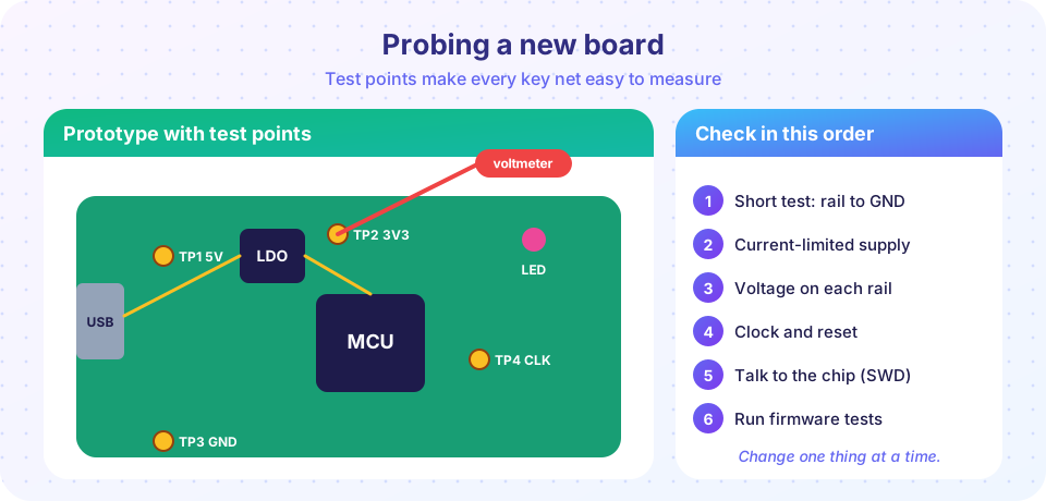
The sequence
- Visual inspection. Use a loupe or microscope. Look for bridges between pins, tombstoned parts, missing parts, reversed polarized parts (diodes, electrolytic capacitors, ICs with a pin 1 dot), and flux residue hiding problems.
- Shorts check (power off). Measure resistance from each power rail to ground with a multimeter. A fresh board with decoupling capacitors will start low and climb as the meter charges them; a steady reading of a few ohms or less on a rail is a short. Find it with a thermal camera, a current injection, or by looking.
- First power with a current limit. Set the bench supply to the expected voltage and a low current limit (for example 3× the expected current, at least tens of mA). Watch the current and feel for warm parts. If the supply enters limit immediately, switch off.
- Measure the rails. Probe at the test points: input, intermediate, and each regulated rail. Compare with the schematic and with the regulator's tolerance.
- Life signs. Check reset is released, oscillators run (scope the clock pin with a ×10 probe), and pull-up and enable pins are where they should be.
- Talk to the chip. Connect the programmer (SWD or JTAG) and read the device ID. If it answers, the core, power and clock are likely fine.
- Run firmware. Start with blink, then exercise each peripheral in turn.
Instruments and technique
Multimeter
Good for DC voltage, continuity (beeper) and resistance. Never measure resistance on a powered board. The diode-test range is handy for finding which pin is shorted to ground (a clean diode drop of about 0.3 to 0.7 V on a pin to ground is normal for protection diodes; 0 V means a short).
Oscilloscope
A scope shows time, which a meter cannot. Rules for trustworthy traces:
- Use a ×10 probe compensated on the scope's calibration output.
- Keep the ground connection short. The long clip lead adds inductance in series with the probe's capacitance, and that LC circuit rings when it sees a fast edge. The ringing is a measurement artifact, not a board fault.
- Match bandwidth: your scope and probe need roughly five times the signal's fundamental, or 0.35 / rise time for edges.
- Measure supply noise at the point of use (the chip's pins), with a short ground spring and the probe set to AC coupling with a scale of about 20 mV/div.
The ringing frequency of a ground lead is f = 1 / (2π√(L·C)). A 15 cm clip lead is on the order of 150 nH; with a 10 pF probe tip that rings near 130 MHz, which can overlay and distort a 5 ns edge. A 1 cm ground spring (about 10 nH) rings at about 500 MHz and is far less damaged by the same edge.
Other tools
A bench supply with a current display, a thermal camera or even a fingertip on a regulator, a logic analyzer for buses, and a USB-serial adapter for debug messages.
Debugging by isolation
When something is wrong, do not shotgun fixes. Instead:
- State what you expected and what you measured. "3.3 V rail reads 0.9 V" is a fact.
- Bisect. Remove or disable half of the loads (lift an inductor, remove a jumper, hold a chip in reset) and see whether the symptom changes.
- Compare with a known-good board or with a simulation.
- Change one thing at a time, and write it down.
- Fix the cause, not the symptom. A hot regulator is often a symptom of a short downstream.
Typical first-board faults: reversed polarity part, missing pull-up, boot pin in the wrong state, solder bridge under a QFN, crystal load capacitors too large, wrong footprint pin mapping. Many are visible once you look where the measurement points.
Common misconceptions
"My signal is ringing, so the board is bad." Check your probe ground first.
"The multimeter says 0 Ω, so it's shorted." A beeper continuity test also beeps through low-value inductors or fuses. Check against the schematic.
"Hot means broken." Some parts are meant to get warm. Compare with the datasheet's dissipation.
Try it
Press Run (or Ctrl + Enter) to see the result here.
Program input · what you'd type while the program runs
Type the answers before you press Run, one per line. Each time the program reads a line (with input()), it gets the next line from this box.
Press Run (or Ctrl + Enter) to see the result here.
Program input · what you'd type while the program runs
Type the answers before you press Run, one per line. Each time the program reads a line (with input()), it gets the next line from this box.
Press Run (or Ctrl + Enter) to see the console output here.
No output.
Check your understanding
Quick check · 5 questions
of 5 answered You scored / 5 · perfect!
-
1. You measure 0.8 ohm from the 3.3 V rail to ground on a board with decoupling capacitors that has had time to charge. What does it suggest?
A steady sub-ohm reading on a rail is a short. -
2. Why use a short ground spring on a scope probe?
Less inductance means higher ringing frequency and less distortion. -
3. What is the best first step for a powered fault?
State the facts, then split the system. -
4. How many bisection tests are needed to locate one bad block among 64?
log2(64) = 6. -
5. Which instrument shows how a rail changes over nanoseconds?
Only a scope shows fast time-domain behavior.
Summary
- Inspect, check for shorts, power with a current limit, then measure rails, life signs and firmware.
- Short ground leads give trustworthy scope traces; long leads ring.
- Isolate by bisection, change one thing at a time, and write observations down.
Next: DFM, DFT and EMC
Track your progress
Create a free account to tick off lessons and pick up where you left off on any device.
of PCB Design and Prototyping lessons completed