


















Lesson 42 of 45 · Projects and Practice
Mini projects: three boards to design yourself
Three self-guided PCB projects, from a blinking LED board to a sensor breakout and a buck module, each with requirements, steps, acceptance tests and stretch goals.
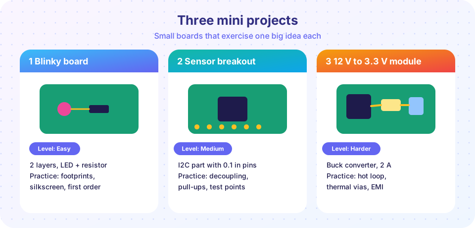
The fastest way to learn PCB design is to design boards and, ideally, to build them. These three mini projects climb in difficulty. Each has requirements, a suggested path, an acceptance test (how you know it works) and stretch goals. You can complete them in CAD only, but ordering a small run of each makes the lessons stick.
What you will learn
- Plan a small board from requirements to acceptance test.
- Practice footprints, decoupling, pull-ups, hot loops and test points.
- Write a short design review for your own board.
Key terms
Acceptance test: a measurable check that proves the board meets its requirements.
Breakout board: a small board that makes a chip's pins easy to use on a breadboard.
Pin header: a row of 0.1 inch (2.54 mm) pins.
Stretch goal: an optional extension once the core works.
Project 1: Blinky board (easy)
Requirements. Powered from a 3.3 V supply or a coin cell; one LED that blinks via a small microcontroller or a 555-style timer; 30 × 20 mm; two layers.
Path. Draw the schematic; compute the LED resistor (R = (Vsupply − Vf)/I; for a 2.0 V red LED at 5 mA from 3.3 V, R = 260 Ω, use 270 Ω); choose 0603 parts; place the parts on a grid; route; add silkscreen labels and two mounting holes.
Acceptance test. LED blinks at the intended rate; supply current is as computed.
Stretch. Add a second LED, a button, and a debug header.
Project 2: I2C sensor breakout (medium)
Requirements. A temperature or pressure sensor with an I2C interface, 3.3 V, pin header at 2.54 mm pitch (so it fits a breadboard), 25 × 20 mm.
Path. Read the sensor datasheet's reference schematic and layout notes; add a 100 nF capacitor at the VDD pin; add pull-ups (2.2 to 4.7 kΩ) with a solder jumper to disable them if multiple boards share a bus; set the I2C address with another jumper; keep the sensor away from heat sources; add test points for SDA and SCL.
Acceptance test. The sensor answers at its address; readings change when you warm it with your finger; the bus rise time is within spec.
Stretch. Add a second sensor with a different address and a level shifter for 5 V hosts.
Project 3: 12 V to 3.3 V buck module (harder)
Requirements. Follow the buck regulator project: 2 A, 500 kHz, two or four layers; add a power-good LED and test points; 40 × 30 mm.
Path. Use the calculators in the buck project for the inductor and divider; draw the hot loop first; add a ground plane; place thermal vias under the IC; check the layout against the manufacturer's evaluation board.
Acceptance test. Output within 2 % at no load and at 2 A; ripple measured with a short ground spring; no component above the datasheet temperature after 10 minutes at full load.
Stretch. Add input reverse protection, an enable switch and a second 5 V output.
Design review template
Before ordering, answer in writing:
- What are the three riskiest parts of the design?
- Which numbers did I calculate, and which did I copy?
- Where do the largest currents loop?
- How will I measure each requirement?
- What did the fab's DRC and an independent viewer find?
Common misconceptions
"Projects must be original." Reuse a reference design for the circuit; the learning is in the layout and verification.
"If it blinks, it is done." An acceptance test is a measurement, not a feeling.
"Skip the review for a small board." Small boards are where one mistake wastes the whole run.
Try it
Press Run (or Ctrl + Enter) to see the console output here.
No output.
Check your understanding
Quick check · 3 questions
of 3 answered You scored / 3 · perfect!
-
1. A 2.0 V LED at 5 mA from 3.3 V needs about what resistor?
(3.3 − 2.0) / 0.005 = 260 ohm. -
2. Why add a solder jumper for I2C pull-ups on a breakout board?
Parallel pull-ups lower the total resistance. -
3. What is an acceptance test?
It proves the requirement, not just the build.
Summary
- Three projects train different skills: basics, bus and decoupling, power layout.
- Write requirements, an acceptance test and a design review for each.
Next: Glossary
Track your progress
Create a free account to tick off lessons and pick up where you left off on any device.
of PCB Design and Prototyping lessons completed