


















Lesson 26 of 45 · Signal and Power Integrity
Decoupling and power planes
Learn where to place decoupling capacitors, how ESL and loop area limit them, how to set a target impedance and how planes and copper width carry current on a PCB.
A digital chip does not draw a steady current. Each time a group of gates switches, the chip pulls a burst of current for a nanosecond or two and then relaxes. The voltage regulator is far away and slow, so something nearby has to supply that burst. That something is the decoupling capacitor: a tiny local reservoir of charge that sits next to the power pin and answers the chip's demand before the regulator even knows it happened.
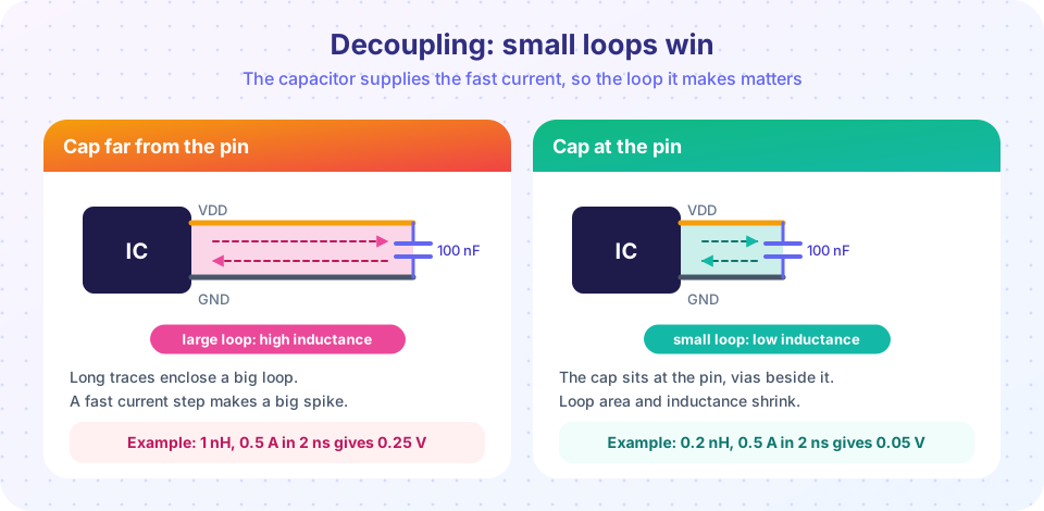
Decoupling works only if the path between the capacitor and the pin is short and low in inductance. Because the burst current changes so fast, even a nanohenry of loop inductance produces a visible voltage dip: ΔV = L · di/dt. This lesson shows how to design the whole power delivery network (PDN): regulator, planes, bulk capacitors and local capacitors, so that the rail stays steady to a few percent.
What you will learn
- Explain the role of decoupling capacitors and their parasitic ESR and ESL.
- Compute the self-resonant frequency of a capacitor.
- Define and calculate a target impedance for a supply rail.
- Place capacitors and vias to keep loop inductance low.
- Size copper for current using IPC-2221.
Key terms
ESR / ESL: equivalent series resistance and inductance, the unwanted resistance and inductance inside every real capacitor.
Self-resonant frequency: where the capacitor's reactance cancels its ESL, f = 1 / (2π√(ESL·C)).
Target impedance: Ztarget = ΔVallowed / ΔItransient, the impedance the PDN must stay below.
Bulk capacitor: a large (microfarad) capacitor that supports slow load changes.
Plane capacitance: the capacitance between two adjacent planes, C = ε0·εr·A / d.
A real capacitor is a series RLC
Between its two terminals a capacitor has capacitance C, plus a small series resistance ESR and a series inductance ESL from its terminals and internal structure. The impedance is
|Z(f)| = √( ESR² + (2π·f·ESL − 1/(2π·f·C))² )
At low frequency the capacitive term dominates and impedance falls as frequency rises. At the self-resonant frequency f0 = 1/(2π√(ESL·C)) the two reactances cancel and the impedance dips down to ESR. Above f0 the part behaves like an inductor and its impedance rises. A 100 nF ceramic with ESL = 0.7 nH resonates near 19 MHz. Above that, it is not a capacitor any more.
This is why you cannot decouple a fast chip with one large capacitor: a 10 µF part has more ESL and resonates around a few MHz, and beyond that it does nothing for the nanosecond bursts. Smaller capacitors extend the useful range upward, but only to tens or low hundreds of MHz. At higher frequencies the planes themselves and the loop inductance of the mounting take over.
Loop inductance is the real limit
The dominant inductance in a decoupling scheme is often not the capacitor but its mounting: the traces and vias that connect it to the pin and to ground. As a very rough guide, a PCB trace contributes around 0.5 to 1 nH per millimeter of length when it is not close to a plane, and a via through a standard 1.6 mm board contributes about 1 nH. Four rules follow:
- Put the capacitor right at the power pin, closer than anything else on that side of the chip.
- Connect it with short, wide traces, or better, with vias directly into the planes next to the pads. Vias beside the pad (or in it, if the fab allows via-in-pad) minimize loop area.
- Use the smallest package that suits the value (0402 or 0603 for 100 nF), since smaller bodies have lower ESL.
- Place the high-frequency capacitor on the same side as the chip and keep the plane pair close beneath it; a thin dielectric between power and ground planes cuts loop inductance and adds free capacitance.
A common starting recipe is one 100 nF capacitor per power pin, one 1 to 10 µF capacitor per few pins or per chip, and a bulk capacitor (10 to 100 µF) near where the supply enters the board. It is only a starting recipe: the right values come from the target impedance.
Target impedance
Instead of guessing, state the requirement. If the rail may deviate by ΔV and the load can change by ΔI in a short time, the PDN must stay below
Ztarget = ΔV / ΔI
For a 3.3 V rail with a 5 % tolerance (0.165 V) and a 0.5 A load step, Ztarget = 0.165 / 0.5 = 0.33 Ω. Now every frequency range needs a source whose impedance is below 0.33 Ω: the regulator handles the slowest changes, bulk capacitors the next range, 1 µF and 100 nF capacitors the high range, and the planes plus the chip's own on-die capacitance the highest.
Planes as capacitors
Two adjacent planes separated by a dielectric of thickness d form a capacitor C = ε0·εr·A/d. A 50 mm × 50 mm pair on 0.1 mm of FR-4 (εr ≈ 4.3) gives about 0.95 nF, with almost no ESL. It is a tiny capacitor, but it is spread across the whole board and responds instantly, which is exactly what the highest frequencies need. This is one more argument for thin power-ground dielectrics in boards that run fast edges.
Delivering DC current
Planes and copper pours also carry the average current, and here the problem is heat and voltage drop, not inductance. Two simple tools:
- Resistance: one square of copper has a sheet resistance of
ρ/t. For 1 oz copper (35 µm), that is about 0.5 mΩ per square at room temperature, regardless of the square's size. A trace 10 squares long and 1 square wide is about 5 mΩ. - IPC-2221 current rule:
I = k · ΔT^0.44 · A^0.725, whereIis current in amperes,ΔTis the temperature rise in °C,Ais the cross-section in mil² andk = 0.048for outer layers (0.024 for inner layers, which cool less well). Solving for area gives the minimum width for a given current and rise. The result is conservative for short traces and optimistic for long ones in hot enclosures, so add margin.
Common misconceptions
"A 10 µF capacitor handles everything up to 100 MHz." Its ESL makes it resonate around a few megahertz. Above that it looks like an inductor.
"Putting the capacitor near the chip is enough." Distance is measured in loop inductance: a capacitor next to the chip with a long thin via to ground can be worse than one slightly farther with a good via.
"Adding more capacitors of the same value is always better." Parallel capacitors can create anti-resonance peaks between values. Check the combined impedance, not just individual parts.
Try it
First, plot the impedance of four typical capacitors. The ESR and ESL values below are typical, illustrative numbers; real parts depend on package and manufacturer, so check the datasheet.
Press Run (or Ctrl + Enter) to see the result here.
Program input · what you'd type while the program runs
Type the answers before you press Run, one per line. Each time the program reads a line (with input()), it gets the next line from this box.
Now combine them in parallel and see whether the network stays below the target. The sharp peaks between capacitors are the anti-resonances mentioned above.
Press Run (or Ctrl + Enter) to see the result here.
Program input · what you'd type while the program runs
Type the answers before you press Run, one per line. Each time the program reads a line (with input()), it gets the next line from this box.
Finally, a copper calculator for how wide a trace must be for a given current.
Press Run (or Ctrl + Enter) to see the console output here.
No output.
Check your understanding
Quick check · 5 questions
of 5 answered You scored / 5 · perfect!
-
1. What does the self-resonant frequency of a capacitor tell you?
At resonance the capacitor's reactance cancels its ESL. Above it, the series inductance dominates. -
2. A 100 nF capacitor has ESL = 0.7 nH. About what is its self-resonant frequency?
f = 1 / (2π·√(0.7e-9 · 100e-9)) = 1 / (2π · 8.37e-9) ≈ 19 MHz. -
3. A 5 V rail allows 4 % deviation and the load steps by 2 A. What is the target impedance?
ΔV = 0.2 V, so Ztarget = 0.2 V / 2 A = 0.1 ohm. -
4. Where should the 100 nF capacitor go?
The loop inductance of the mounting limits performance, so the capacitor must be right at the pin with a short return. -
5. What is the sheet resistance of 1 oz (35 µm) copper at room temperature?
ρ/t ≈ 1.72e-8 / 35e-6 ≈ 0.49 mΩ per square, independent of the square's size.
Summary
- Decoupling capacitors supply the nanosecond current bursts that the regulator cannot.
- Real capacitors are series RLC parts and stop helping above their self-resonant frequency.
- Mounting inductance (traces and vias) often dominates; place capacitors at the pin with short, direct vias.
- Set a target impedance
ΔV / ΔIand check the combined network against it. - Planes give free, low-inductance capacitance; copper width follows IPC-2221 for current and heat.
Next: Chapter 5 review
Track your progress
Create a free account to tick off lessons and pick up where you left off on any device.
of PCB Design and Prototyping lessons completed