


















Lesson 12 of 45 · Components and Footprints
Passives and Preferred Values
Learn the E6, E12 and E24 preferred-value series, resistor tolerance and power, and capacitor voltage ratings and dielectrics (C0G, X7R) for PCB design.
Resistors, capacitors and inductors are called passive components because they do not amplify. They make up the great majority of the parts on a board, often more than 80 percent of the BOM lines. They look boring, yet most of the practical decisions in PCB design happen here: which value, how accurate, what voltage and what size.
You cannot buy a resistor of any arbitrary value in any quantity. Manufacturers make parts in preferred values, and you design with those. In this lesson you learn the pattern behind the values, how tolerance and ratings work and why capacitors are more complicated than they look.
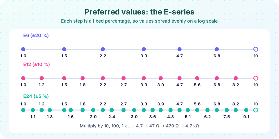
What you will learn
- How the E-series is built and what its tolerance means
- How to pick resistors by value, tolerance, power and voltage
- How capacitor dielectrics (C0G, X7R, X5R) behave
- Why capacitor voltage rating and DC bias matter
Key terms
E-series: standard sets of values per decade (E6, E12, E24, E48, E96, E192), named by how many values they hold.
Tolerance: how far the real value may differ from the marked one (for example ±1 %).
Power rating: the heat a part can dissipate continuously (for a chip resistor often 1/16 W to 1/4 W).
Dielectric: the insulating material in a capacitor; its type sets stability.
DC bias effect: the drop in a ceramic capacitor's capacitance when a DC voltage is applied.
Preferred values and the E-series
Imagine making resistors with 20 percent accuracy. If you offered 100 Ω and 105 Ω, one resistor could be either. It would be wasteful to offer them both. Instead, space the values so that each step is about equal to the tolerance, and every possible resistance is covered. A 20 % part needs about six steps per decade: E6. A 10 % part needs twelve (E12); 5 % needs 24 (E24), and so on up to E192.
The ideal spacing is a geometric progression: the nth value of an EN series is about 10^(n/N). For E12 that is 1.00, 1.21, 1.47, 1.78, 2.15, 2.61, .... The standard rounds some of these to values people could remember (2.2, 2.7, 3.3, 3.9, 4.7, 5.6, 6.8, 8.2), so the printed table differs a little from the exact formula. You will see this difference in the first example.
Each decade is the same list multiplied by 10: 4.7, 47, 470, 4.7 k, 47 k, 470 k, 4.7 M. When you calculate a resistor and get an odd result, round to the nearest value in the series that is tolerable, then check the effect.
Today, 1 % resistors in the E96 series cost almost the same as 5 % ones, so many designs use 1 % everywhere and avoid thinking about it. For signal paths and voltage dividers, 1 % is a good default. For LED current limiting and pull-ups, 5 % is plenty.
Choosing a resistor
Four numbers define a chip resistor:
- Value: from the E-series.
- Tolerance: ±5 %, ±1 %, ±0.1 % for precision.
- Power rating: a 0603 is typically rated 1/10 W (0.1 W), a 0805 1/8 W, a 1206 1/4 W. Derate: stay under about half the rating. Calculate power with
P = I² × RorV² / R. - Maximum voltage: a chip resistor has a limit on working voltage, commonly 50 V to 200 V depending on size. High voltages across a small part can cause failures even at low power.
Temperature coefficient (TCR) matters for precision circuits, with 100 ppm/°C common for general parts and 25 ppm/°C or better for precision ones.
Capacitors are subtler
A capacitor stores charge, and its main number is capacitance in farads (usually pF, nF or µF). Ceramic multilayer ceramic capacitors (MLCCs) are the default on modern boards because they are small, cheap and have low parasitic inductance. Their ceramic type decides behavior.
| Dielectric | Stability | Typical use |
|---|---|---|
| C0G (also NP0) | Very stable, about ±30 ppm/°C, no voltage effect | Timing, filters, RF; small values (up to about 100 nF) |
| X7R | ±15 % over −55 to +125 °C; some voltage effect | General decoupling, bulk capacitance |
| X5R | ±15 % over −55 to +85 °C | Consumer decoupling |
| Y5V, Z5U | Large changes with temperature and voltage | Avoid for new designs |
The code is a three-character label: the first two characters give the temperature range and the last the change in capacitance. You do not need to memorize it: remember C0G is "precise", X7R is "good enough for decoupling", and Y5V is "avoid".
Voltage rating must exceed the highest voltage the capacitor sees, with margin. A common rule is to choose a rating at least twice the working voltage for ceramics. This matters because of the DC bias effect: a 10 µF X5R capacitor rated for 6.3 V can lose more than half its capacitance when you apply 5 V. A 10 µF capacitor in a 0603 package rated 6.3 V may provide only 3 to 4 µF at 5 V. Choose a higher voltage rating, a larger package or check the manufacturer's bias curve.
Electrolytic and tantalum capacitors have polarity: reverse voltage can damage them or cause a fire. Mark polarity clearly on the silkscreen and check it on the datasheet.
Common misconceptions
"A 10 µF capacitor is 10 µF everywhere." Temperature, DC bias and age all change real capacitance, sometimes drastically for X5R and X7R.
"Higher voltage rating costs me nothing." It costs size and money, but it is usually worth it: a 16 V rating for a 5 V rail is typical for ceramics.
"Resistors are all alike." Tolerance, power, voltage rating and temperature coefficient matter for dividers, sensors and high-voltage circuits.
Try it
The first example compares the exact E-series formula with the standard E12 values. Notice where the printed standard departs from the pure formula and by how much.
Press Run (or Ctrl + Enter) to see the result here.
Program input · what you'd type while the program runs
Type the answers before you press Run, one per line. Each time the program reads a line (with input()), it gets the next line from this box.
The second example uses the series to design a voltage divider. A divider gives Vout = Vin × R2 / (R1 + R2). The code searches all pairs of E24 values for the one closest to a target output, then shows how the best error depends on the series.
Press Run (or Ctrl + Enter) to see the result here.
Program input · what you'd type while the program runs
Type the answers before you press Run, one per line. Each time the program reads a line (with input()), it gets the next line from this box.
Check your understanding
Quick check · 5 questions
of 5 answered You scored / 5 · perfect!
-
1. How many values per decade does the E12 series have?
E12 has twelve values per decade and about 10 % tolerance. -
2. Which resistor value is NOT in the standard E12 series?
3.0 appears in E24 but not in E12. -
3. Which ceramic dielectric is the most stable?
C0G has tiny temperature drift and no voltage effect, but only for small values. -
4. What is the DC bias effect?
High-capacitance X5R/X7R parts can lose a large part of their value near the rated voltage. -
5. A resistor dissipates 80 mW. Which chip size is the best fit with derating?
Keep power below about half the rating, so 80 mW suggests at least 1/8 W.
Summary
- E-series values are spaced geometrically: E6, E12 and E24 for 20 %, 10 % and 5 %.
- Choose resistors by value, tolerance, power (with derating) and voltage.
- Use C0G for precision, X7R for general use and avoid Y5V; mind the DC bias effect.
- Pick capacitor voltage ratings with margin, often twice the working voltage.
Track your progress
Create a free account to tick off lessons and pick up where you left off on any device.
of PCB Design and Prototyping lessons completed