


















Lesson 23 of 45 · Signal and Power Integrity
Chapter 5 overview: signal and power integrity
Why fast edges ring, why neighbors interfere and why supply rails droop, and the five lessons that teach you to prevent each problem on a real printed circuit board.
A board that passes every connectivity check can still fail. The schematic says that pin 4 connects to pin 9, and the layout does exactly that, yet the receiver sees a waveform full of ringing, a neighboring trace picks up a phantom pulse, or the supply sags for a few nanoseconds every time the processor wakes up. These are not wiring mistakes. They are physics problems that appear once signals change fast enough for a trace to behave like a transmission line, and once currents change fast enough for a few nanohenries of inductance to matter.
This chapter is the bridge between "the netlist is correct" and "the board works". You will learn to think about every trace as a path with an impedance, to follow the return current (the half of the circuit that the schematic hides), to keep neighbors apart, and to deliver clean power to every chip.
What you will learn
- Explain why high-speed signals need controlled impedance and when a trace counts as "long".
- Follow the return current of any signal and avoid layouts that break it.
- Estimate and reduce crosstalk between neighboring traces.
- Place decoupling capacitors and size a power delivery network.
- Use calculators and simulations to check a layout idea before you spend money on a board.
Key terms
Signal integrity (SI): the quality of a signal as it travels from driver to receiver (shape, timing, noise).
Power integrity (PI): the quality of the supply voltage that the chips actually see on their pins.
Characteristic impedance (Z0): the ratio of voltage to current of a wave travelling along a line, in ohms.
Return path: the route that the current takes back to its source, usually through the nearest plane.
Crosstalk: unwanted coupling of a signal from one trace into another.
The big picture
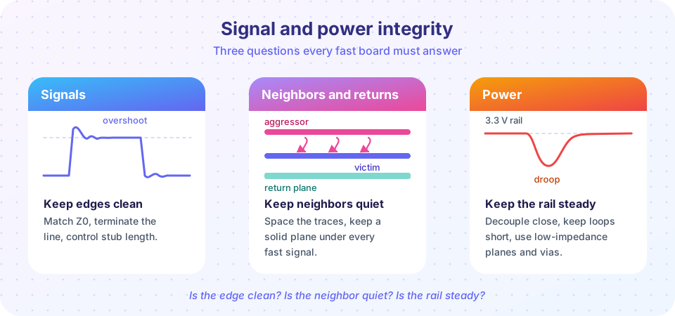
Every digital edge contains much higher frequencies than the clock rate suggests. A 3.3 V signal with a 1 ns rise time has significant energy up to roughly 350 MHz, whether the clock runs at 1 kHz or 100 MHz. At those frequencies copper is not a wire; it is a distributed network of inductance and capacitance. That has three consequences, and they structure the chapter:
- Signals reflect wherever the impedance changes. Mismatch between driver, trace and receiver creates overshoot, undershoot and ringing.
- Fields leak sideways. A fast edge on one trace couples into its neighbors through mutual capacitance and mutual inductance.
- Supply current is not constant. Chips draw current in sharp bursts, and the loop that carries those bursts has inductance, so the voltage at the pin dips.
Why boards fail even when the netlist is right
Physics, not wiring mistakes
Lesson 1: impedance and reflections
Lesson 2: crosstalk and return paths
Lesson 3: decoupling and planes
What each lesson covers
| Lesson | Question it answers |
|---|---|
| Impedance and reflections | What is Z0, how do I get 50 Ω, and when do I need termination? |
| Crosstalk and return paths | Where does the current go back, and how far apart should traces be? |
| Decoupling and power planes | How many capacitors, where, and how stiff must the supply be? |
| Chapter review | A one-page poster and ten mixed questions. |
Common misconceptions
"Signal integrity only matters for gigahertz designs." It matters whenever the edge is fast compared with the trace delay. A 10 MHz microcontroller with a 2 ns edge can ring badly on a 15 cm trace.
"The ground plane is just 'ground'." It is the return conductor of every signal above it. Cutting it changes the circuit.
"More capacitors always means a cleaner supply." Capacitors have inductance and interact with each other. Placement and loop area matter more than the count.
Try it
The first demo shows why rise time, not clock frequency, sets the bandwidth you must design for.
Press Run (or Ctrl + Enter) to see the console output here.
No output.
The second demo is an interactive ringing visualizer. Drag the slider to change the source resistance and see how a mismatch makes the edge overshoot.
Check your understanding
Quick check · 4 questions
of 4 answered You scored / 4 · perfect!
-
1. Which property of a digital edge mainly determines whether a trace behaves like a transmission line?
A trace acts as a transmission line when the edge is fast compared with the time the signal needs to travel along it. -
2. What is the return path of a signal?
Every current flows in a loop. The return current is the part that comes back, and it matters as much as the forward trace. -
3. A 1 ns rise time corresponds to roughly what bandwidth?
Bandwidth is about 0.35 divided by the rise time, so 0.35 / 1 ns = 350 MHz. -
4. Which problem is a power integrity problem?
Power integrity concerns the quality of the supply voltage at the pins of the chips.
Summary
- Fast edges, not slow clocks, create signal integrity problems.
- Reflections, crosstalk and supply droop are the three classic failures.
- Every signal has a return current; the layout must give it a clean path.
- The next lessons give you formulas, rules of thumb and simulations for each problem.
Track your progress
Create a free account to tick off lessons and pick up where you left off on any device.
of PCB Design and Prototyping lessons completed