


















Lesson 30 of 45 · Manufacturing and Assembly
Gerbers and fabrication files
Learn what is inside a Gerber package, how drill, BOM and pick-and-place files work, and how to check a fabrication package before ordering a PCB.
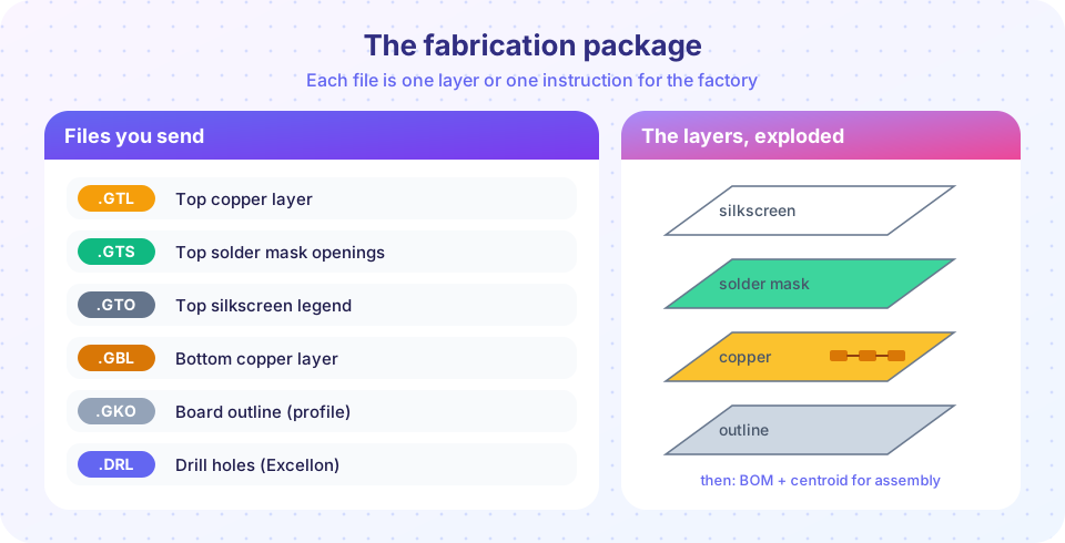
Your CAD project is not what the factory receives. A fab shop cannot open your design tool's native files, and it should not need to. Instead you export a neutral fabrication package: one image file per copper, mask and silkscreen layer, a drill file that says where the holes go, an outline, and, for assembly, a bill of materials and a placement file.
This lesson explains each file in plain terms, shows you how little a Gerber actually contains, and gives you a checklist for catching mistakes before they become boards.
What you will learn
- Name the files in a standard fabrication package and what each describes.
- Read a tiny Gerber file by hand.
- Explain what a BOM and a centroid (pick-and-place) file contain.
- Run a pre-order checklist.
Key terms
Gerber (RS-274X, X2): a text format that draws one layer using apertures, flashes and strokes.
Excellon: the standard drill file format, listing tools (diameters) and hole coordinates.
BOM: bill of materials; each line gives a part, quantity, reference designators and manufacturer number.
Centroid / CPL / pick-and-place file: part reference, X, Y, rotation and side for the placement machine.
Panelization: arranging several copies of a board into one manufacturing panel.
The package
| File (KiCad-style names) | What it holds |
|---|---|
Top copper .GTL, bottom copper .GBL |
Traces, pads and pours on outer layers |
Inner copper .G2, .G3 |
Plane or signal layers |
Top/bottom solder mask .GTS / .GBS |
Openings where mask is removed (pads) |
Top/bottom silkscreen .GTO / .GBO |
Legend text and symbols |
Paste .GTP / .GBP |
Stencil apertures for assembly |
Outline .GKO or Edge.Cuts |
The board profile |
Drill .DRL (Excellon) |
Plated and non-plated holes by tool |
File extensions vary by CAD tool, but fabs identify layers by their content (X2 attributes) or by a name you provide in a readme. A zip of all these files is what you upload.
What is inside a Gerber?
A Gerber is a program for an imaginary plotter. It first sets units and number format, then defines apertures (shapes), and then moves, draws (D01), jumps (D02) or flashes (D03, stamps the current aperture). A tiny example:
%FSLAX24Y24*%
%MOMM*%
%ADD10C,0.25*%
%ADD11R,1.60X1.00*%
D10*
X0Y0D02*
X100000Y0D01*
X100000Y50000D01*
D11*
X0Y50000D03*
X100000Y100000D03*
M02*
FSLAX24 means two integer and four decimal digits, so 100000 is 10.0000 mm. D10 selects a 0.25 mm round aperture used for the track, and D11 a 1.6 × 1.0 mm rectangular pad. Everything you see in a Gerber viewer comes from lines like these.
Drill, BOM and centroid
- Drill file. Lists tools (
T1C0.300is tool 1, 0.300 mm) and X,Y positions. Plated holes (vias, through-hole pins) and non-plated holes (mounting) are usually separate files so the fab knows which to plate. - BOM. One line per unique part: quantity, reference designators (
C1, C2, C5), value, footprint, and a manufacturer or distributor part number. The part number is what removes ambiguity: "100 nF" can be dozens of different parts. - Centroid (CPL). For every placed part: reference, X, Y, rotation, and top or bottom side. Rotation conventions differ between CAD tools and assemblers, so preview the placement before you pay.
Common file traps
- Rotation mismatches. Polarized parts and ICs show up rotated 90° or 180° because of differing zero-rotation definitions. Check the assembler's preview.
- Missing outline. Without a closed outline the fab guesses.
- Mask and paste on the wrong side, or paste openings on non-solder pads.
- Plated slots exported as drill holes of the wrong shape.
- Units confusion between mm and inches.
Pre-order checklist
- Run DRC in the CAD tool with the fab's rules loaded.
- Export Gerbers, drill, BOM and CPL fresh from the final design.
- Open every file in an independent Gerber viewer and compare it with the CAD view: layers aligned, outline closed, drill visible through pads.
- Check dimensions and layer count against the quote.
- Check the stackup and impedance notes if relevant.
- Add a readme with the layer order, finish, mask color and thickness.
- Preview the assembly: parts on the right pads, orientation, pin 1 markers.
Common misconceptions
"The fab checks my design." They check manufacturability with automated tools, not whether your circuit works.
"Any viewer shows the same thing." Different viewers render clear polarity and apertures differently; use at least one independent of your CAD tool.
"The BOM can just say 100 nF." Specify package, voltage, dielectric and a part number, or the assembler picks for you.
Try it
This mini Gerber reader parses the sample above and draws it. It is a toy: it handles only circles, rectangles, straight draws and flashes.
Press Run (or Ctrl + Enter) to see the result here.
Program input · what you'd type while the program runs
Type the answers before you press Run, one per line. Each time the program reads a line (with input()), it gets the next line from this box.
A BOM and a centroid file must agree. This checker finds parts that appear in one but not the other.
Press Run (or Ctrl + Enter) to see the result here.
Program input · what you'd type while the program runs
Type the answers before you press Run, one per line. Each time the program reads a line (with input()), it gets the next line from this box.
Press Run (or Ctrl + Enter) to see the console output here.
No output.
Check your understanding
Quick check · 4 questions
of 4 answered You scored / 4 · perfect!
-
1. In a Gerber file, what does a D03 command do?
D01 draws, D02 moves, D03 flashes the aperture. -
2. Which file tells the assembler where to put each component?
The centroid file lists reference, X, Y, rotation and side for each part. -
3. Why should you open your Gerbers in an independent viewer?
An independent viewer shows exactly what the factory will see. -
4. What is a common cause of rotated polarized parts in assembly?
Libraries define part orientation differently, so the CPL needs checking against the assembler's preview.
Summary
- A fabrication package is Gerber layers, an outline, drill files, and for assembly a BOM and a centroid file.
- Gerbers are simple programs of apertures, draws and flashes.
- Specific part numbers and checked rotations keep assembly right.
- Always preview the package in independent tools before ordering.
Track your progress
Create a free account to tick off lessons and pick up where you left off on any device.
of PCB Design and Prototyping lessons completed