


















Lesson 6 of 45 · From Schematic to Board
Chapter 2 Overview: From Schematic to Board
Overview of chapter 2: how a schematic becomes a netlist and then a board, with a map of the four lessons on capture, netlists, ERC, BOM and rules.
The schematic and the board describe the same circuit in two different languages. The schematic says what connects to what. The board says where everything sits and how the copper runs. The bridge between them is the netlist, a list of connections, together with a footprint for each part. Understanding this bridge removes a lot of confusion: for example, why you can move a part on the board without changing the circuit, and why a wrong wire in the schematic cannot be fixed by clever routing.
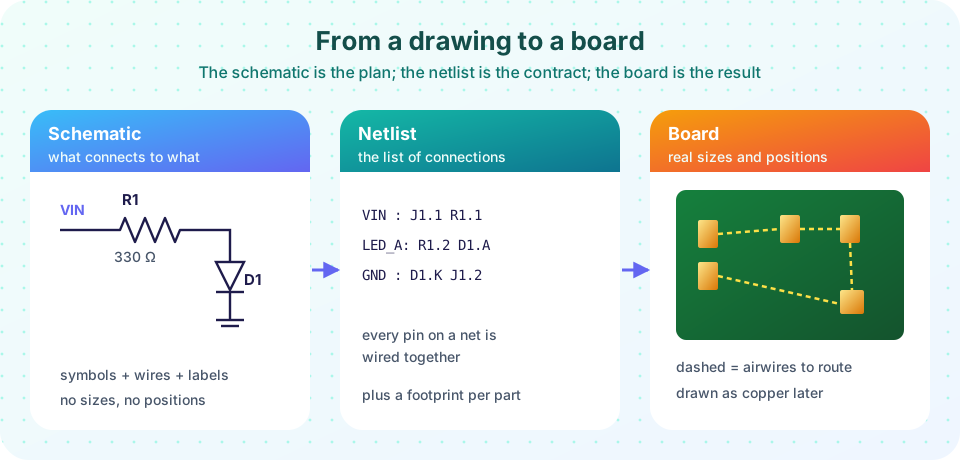
Three forms of one circuit
Capture
Check
Set up the board
What you will learn in this chapter
- How to draw a clean, readable schematic with symbols, wires, labels and reference designators
- What a netlist is and how electrical rules checks catch mistakes
- How a bill of materials follows from the schematic
- How to set board size, layers and design rules before the first trace
The lessons
- Schematic Capture: symbols, reference designators, values, power flags and layout of a readable sheet.
- Netlists, ERC and the BOM: how connections become data, which mistakes ERC finds and how the parts list is produced.
- Board Setup, Stack-up and Design Rules: outline, layers, minimum widths and clearances taken from your fab.
- Chapter 2 Review: recap and ten questions.
The big idea: separate the "what" from the "where"
Beginners sometimes try to design the layout directly. The professional habit is to separate concerns. In the schematic you decide the logic and the values. In the layout you decide the geometry. When something is wrong you can ask which kind of problem it is. A short between two nets is a schematic or footprint problem. A trace too close to another is a layout problem. A part that cannot be soldered is a footprint or library problem.
You will also meet the idea of a single source of truth. The schematic is the master. When you change a value or add a part, you change it in the schematic and push the change to the board ("Update PCB from schematic"). If you edit both separately they drift apart, and the board no longer matches the circuit you reviewed.
Check your understanding
Quick check · 3 questions
of 3 answered You scored / 3 · perfect!
-
1. What does the netlist contain?
A netlist lists connections, not geometry. -
2. Where should a value change be made?
The schematic is the single source of truth. -
3. A short between two nets that should be separate is most likely a
Connections come from the schematic and from pad numbering in footprints.
Summary
- Schematic, netlist and board are three views of one circuit.
- The schematic is the master; update the board from it.
- This chapter covers capture, checks, the BOM and board setup.
Next: Schematic Capture
Track your progress
Create a free account to tick off lessons and pick up where you left off on any device.
of PCB Design and Prototyping lessons completed