


















Lesson 37 of 45 · Complete Projects
Chapter 8 overview: complete projects
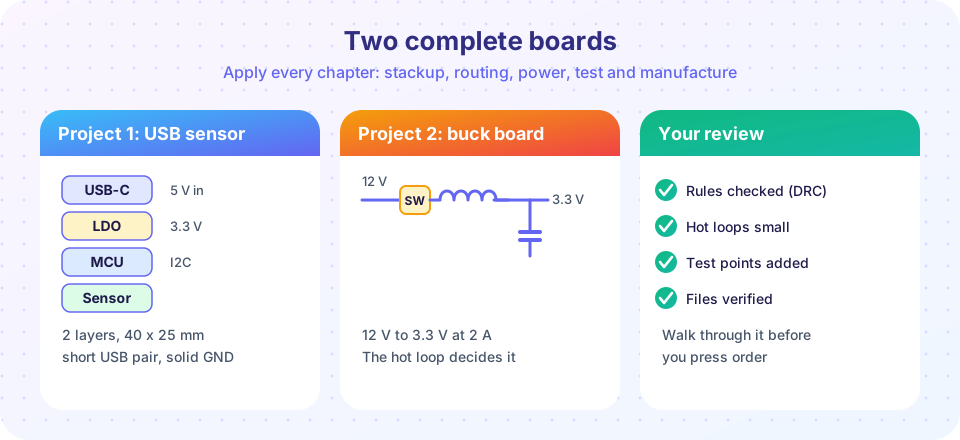
Two end-to-end PCB projects, a USB-C powered sensor board and a 12 V to 3.3 V buck regulator board, plus a pre-order review, applying every earlier chapter.
Concepts become skills when you use them together. In this chapter you will design two complete boards on paper: a small USB-C powered sensor board and a 12 V to 3.3 V buck regulator board. They are deliberately different. The first is dominated by connectors, power conditioning and a bus; the second by one noisy current loop and heat.
For each project you will go from requirements to block diagram, parts, schematic decisions, stackup, placement, routing priorities, test points and the files you would send to a manufacturer. The numbers are worked out with calculators you can run and change.
What you will learn
- Turn requirements into a block diagram and a floorplan.
- Choose parts and values with calculations, not guesses.
- Prioritize placement and routing on a small two-layer board.
- Run a pre-order review that catches the usual mistakes.
Key terms
Requirements: measurable statements of what the board must do (input range, output current, size).
Floorplan: a rough placement of blocks before detailed layout.
Hot loop: the loop carrying pulsed switching current in a converter.
CC pins: USB-C configuration channel pins that signal the role and power capability.
Design review: a structured read-through of the schematic and layout before ordering.
The projects
Project 1: USB-C sensor board
Small, two layers, 40 x 25 mm
Project 2: buck regulator
Review
What each lesson covers
| Lesson | Focus |
|---|---|
| USB-C sensor board | CC resistors, protection, LDO dissipation, I2C pull-ups, USB routing on two layers. |
| Buck regulator board | Inductor, capacitors, feedback divider, hot loop and thermal design. |
| Chapter review | The poster and ten questions. |
Common misconceptions
"A small board is an easy board." Small boards pack the problems closer: heat, noise and test access all get tighter.
"I can pick values later." Many layout choices (trace width, inductor size) depend on values. Decide early.
"Copy the reference layout and it will work." Reference layouts work when you copy the intent (loop, return paths), not just the part positions.
Try it
Press Run (or Ctrl + Enter) to see the console output here.
No output.
Check your understanding
Quick check · 3 questions
of 3 answered You scored / 3 · perfect!
-
1. What should come first in a project?
Requirements drive every later choice. -
2. What is a hot loop?
In a converter it is the path of the fast-changing current. -
3. Why is a small board not necessarily easier?
Everything is closer together.
Summary
- Start with requirements, a block diagram and a floorplan.
- Calculate values for power, bus and filters before routing.
- Run a structured review before ordering.
Next: USB-C sensor board
Track your progress
Create a free account to tick off lessons and pick up where you left off on any device.
of PCB Design and Prototyping lessons completed