


















Lesson 31 of 45 · Manufacturing and Assembly
Assembly, soldering and reflow
Understand solder paste printing, stencil design, pick and place, the reflow temperature profile, common defects like tombstoning and bridging, and hand soldering basics.
A bare board has copper pads, but no circuit. Assembly turns it into one, and for surface-mount parts the process is surprisingly elegant: print a gray paste on every pad, drop the parts on the paste, and heat the whole board until the paste melts into shiny joints. Surface tension does the fine alignment for you, which is why a placement machine that is a few tenths of a millimeter off still yields good boards.
This lesson walks through the steps, shows you the temperature profile that makes it work, and teaches you to recognize the defects that your own layout choices can cause.
What you will learn
- Explain stencil printing and compute aperture area ratio.
- Describe the four zones of a reflow profile and typical limits.
- Identify tombstoning, bridging, voids and insufficient solder, and their causes.
- Solder a joint by hand with the right technique.
Key terms
Stencil: a thin steel foil with openings (apertures) matching the pads, used to print paste.
Liquidus: the temperature above which the alloy is fully liquid (217 °C for SAC305 lead-free solder; 183 °C for tin-lead Sn63Pb37).
Wetting: solder flowing and bonding to a clean metal surface.
Tombstoning: a small chip part lifting on one end during reflow.
Area ratio: aperture opening area divided by aperture wall area; it predicts how well paste releases.
Step by step
- Paste printing. The stencil is aligned to the board and a squeegee pushes paste through the apertures. Paste is roughly 50 % solder by volume (about 90 % by weight), the rest flux and solvent. Typical stencil thickness is 0.1 to 0.13 mm (4 to 5 mil); finer pitch parts need thinner foil.
- Placement. A pick-and-place machine takes each part from a reel, finds its orientation by camera, and presses it into the paste. The paste's tackiness holds parts in place.
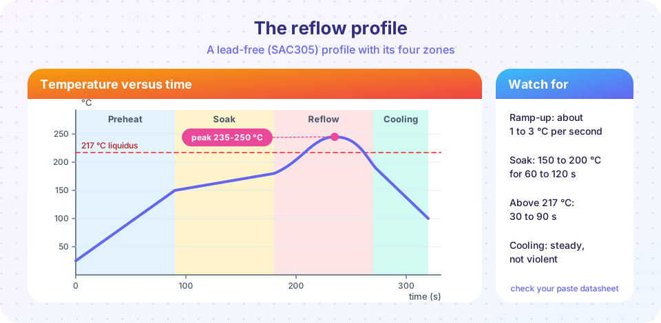
- Reflow. The board rides a conveyor through an oven with several heated zones. The profile has four stages: preheat (ramp gently, at about 1 to 3 °C per second, to avoid thermal shock); soak (about 150 to 200 °C for 60 to 120 s, activating flux and equalizing temperature); reflow (rise above the liquidus, peak around 235 to 250 °C for lead-free, time above liquidus typically 30 to 90 s); and cooling (controlled, because fast cooling stresses parts and slow cooling coarsens the joint).
- Inspection. Automated optical inspection (AOI) checks presence, position and joint shape. X-ray looks under BGAs and QFN thermal pads.
- Through-hole and rework. Through-hole parts are soldered by wave, selective or hand soldering. Faulty parts are removed with hot air and replaced.
Always follow the paste maker's datasheet and the component's moisture sensitivity level (MSL): parts that absorbed moisture must be baked, or they can crack ("popcorn") in the oven.
Designing the stencil: area ratio
For a rectangular aperture of length L, width W and foil thickness T:
area ratio = (L·W) / (2·(L + W)·T)
Paste releases cleanly when the ratio is above about 0.66 (and the aspect ratio W / T is at least 1.5). A 0.5 mm × 0.5 mm aperture in 0.12 mm foil gives 0.25 / (2·1.0·0.12) = 1.04: fine. A 0.25 mm × 1.0 mm fine-pitch aperture in 0.12 mm gives 0.25 / (2·1.25·0.12) = 0.83, but its aspect ratio is 0.25 / 0.12 = 2.1, still acceptable. Reduce the foil to 0.1 mm for very fine pitch.
What goes wrong, and why
| Defect | Look | Typical cause |
|---|---|---|
| Tombstoning | Chip stands on one end | Unequal pad sizes, unequal heat or a trace pulling heat from one pad |
| Bridging | Solder between adjacent pins | Too much paste, mask dam missing, misplacement |
| Insufficient solder | Dull, small fillet | Clogged aperture, tiny pad, poor wetting |
| Voids | Bubbles in the joint (X-ray) | Trapped flux gas, big thermal pads, wrong profile |
| Head-in-pillow | Ball sits on paste without merging | Warped BGA or board, oxidation |
| Solder balls | Small spheres near parts | Paste slump, too fast preheat |
Notice that most of these start in the layout: footprints that follow the manufacturer's land pattern, symmetric pads with symmetric copper connections, solder mask dams between fine-pitch pads, and thermal pads split into small paste windows.
Hand soldering
For prototypes you will solder by hand. Set the iron to around 320 to 350 °C for lead-free solder (lower for leaded). Clean and tin the tip. Touch the iron to both the pad and the lead so they heat together, feed solder to the joint, not the tip, then remove solder and iron. A good joint is smooth, shiny (lead-free is slightly duller) and concave, taking two to three seconds. Add flux for fine-pitch drag soldering and clean flux residue afterward.
Common misconceptions
"More paste is safer." Excess paste causes bridges and solder balls. The target is the volume the pad design calls for.
"A higher peak temperature makes a better joint." Beyond the paste and component limits it damages parts and board. Hit the window; do not exceed it.
"Lead-free solder is just like leaded." It melts higher (217 °C versus 183 °C), wets less eagerly, and gives a duller joint, so profiles and technique differ.
Try it
Press Run (or Ctrl + Enter) to see the result here.
Program input · what you'd type while the program runs
Type the answers before you press Run, one per line. Each time the program reads a line (with input()), it gets the next line from this box.
Press Run (or Ctrl + Enter) to see the console output here.
No output.
Check your understanding
Quick check · 5 questions
of 5 answered You scored / 5 · perfect!
-
1. What is the liquidus temperature of SAC305 solder?
SAC305 is fully liquid above about 217 °C. Tin-lead eutectic melts at 183 °C. -
2. Which is a typical cause of tombstoning?
If one end of the part wets first, its surface tension lifts the other end. -
3. A 0.5 mm × 0.5 mm aperture in 0.12 mm foil. What is the area ratio?
0.25 / (2 · 1.0 · 0.12) = 1.04. -
4. Where should you apply solder when hand soldering?
Heat pad and lead together, feed solder to the joint, and let it flow. -
5. Why is an MSL bake needed for some parts?
Trapped moisture turns to steam in reflow and can crack packages.
Summary
- Assembly is paste printing, placement, reflow and inspection.
- Reflow has four zones; the key limits are ramp rate, soak and a short time above liquidus.
- Many defects begin in layout: symmetric pads, proper land patterns and mask dams help.
- Hand soldering needs the right tip temperature and heating both pad and lead.
Next: Chapter 6 review
Track your progress
Create a free account to tick off lessons and pick up where you left off on any device.
of PCB Design and Prototyping lessons completed