


















Lesson 1 of 45 · Getting Started
Course Map: How to Study PCB Design
See the whole PCB design course at a glance: who it is for, what you need to know first, the nine chapters and a study plan for building real boards.
A printed circuit board, or PCB, is the part of an electronic device that most people never see and nearly everyone depends on. Inside your phone, your keyboard, your car and your washing machine there is a thin sheet of fiberglass with copper lines on it, holding tiny parts in exactly the right places. Somebody had to design that sheet. This course teaches you how.
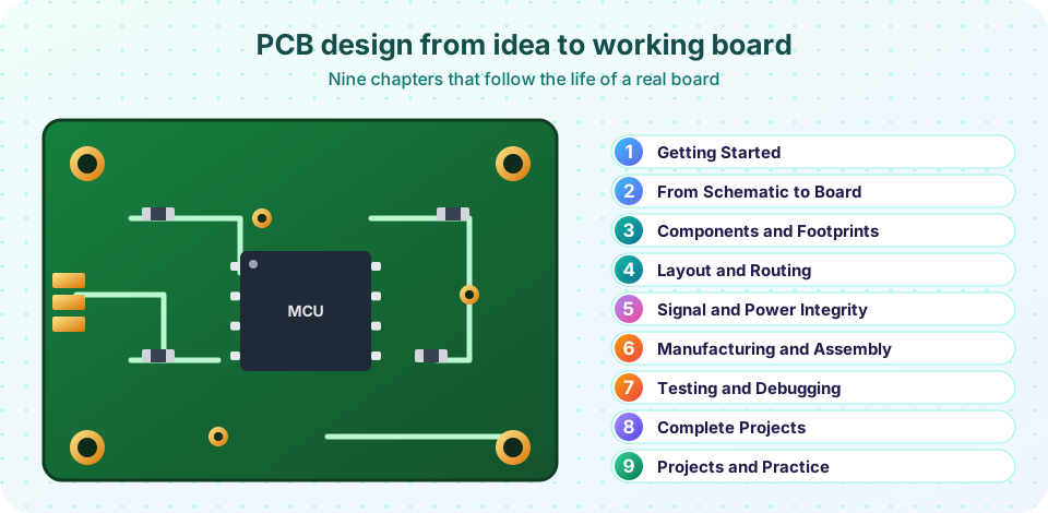
You will move from "I have a circuit idea" to "I hold a working board that I designed". Along the way you will learn the vocabulary, the free tools, the rules of thumb that professionals use every day and the calculations behind them. The first four chapters are in this part of the course; later chapters cover signal and power integrity, manufacturing, testing and complete projects.
This course teaches general electronics design practice. Mains voltages and safety-critical products (medical devices, vehicles, anything that can hurt someone if it fails) need formal training, standards and testing that go beyond a tutorial. Start with low-voltage hobby and learning projects.
What you will learn
- Who this course is for and what you should already know
- How the nine chapters fit together into one design journey
- A study method that mixes reading, calculation and building
- What tools you need (all of them free)
Key terms
PCB (printed circuit board): a board of insulating material with copper conductors that connects and supports electronic parts.
EDA (electronic design automation): the software used to draw schematics and lay out boards. KiCad is a free example.
Schematic: a diagram that shows how parts connect electrically, without caring where they sit.
Layout: the physical arrangement of parts and copper on the board.
Fab (fabrication house): the factory that manufactures your bare board from files you send.
Who this course is for
This course is for you if you are one of these people:
- A student of electronics, physics or computer engineering who has built circuits on a breadboard and now wants a "real" board.
- A software developer who has used Arduino or Raspberry Pi and wants to design a custom device.
- A hobbyist who wants to turn a prototype into something neat and repeatable.
- An engineer from another field who needs to understand what the electronics team does.
You do not need a degree. You do need to be comfortable with three ideas: voltage is like pressure, current is like flow, and resistance limits the flow. If you know Ohm's law, V = I × R, and you can read a simple circuit diagram, you can start now. Where a calculation appears, it is explained, and every runnable example is a small simulation or calculator you can change.
The nine chapters
The chapters follow the order of a real project. You first learn what a board is made of, then you capture the circuit, choose parts, place and route them, and make sure it works electrically. After that you manufacture it, test it and finish with complete projects.
The journey
Chapters 1 and 2
Chapters 3 and 4
Chapters 5 and 6
Chapters 7 to 9
How to study
Read a lesson in one sitting, then do the "Try it" examples. Change the numbers. If a calculator says a trace must be 0.78 mm wide, try 0.3 mm and see what happens to the temperature rise. A formula you have broken on purpose is a formula you remember.
A good rhythm is one lesson a day. After each chapter, read the chapter review and take its quiz. If you miss a question, go back to the lesson it came from.
Most important: build something. By the end of Chapter 4 you can draw a small board. Even if you never order it, laying it out teaches you more than any amount of reading. The free tool KiCad (Windows, macOS, Linux) is a good choice; the ideas apply equally to Altium, Eagle, EasyEDA and others.
Common misconceptions
"PCB design is just drawing lines between parts." Routing is a small part of the job. Most of the quality of a board comes from decisions made earlier: part choice, placement and the layer stack-up.
"If it works on the breadboard it will work on the PCB." A breadboard adds stray capacitance and loose contacts, but a PCB has its own behaviors: fast edges, noise and heat all depend on layout. Chapter 5 explains why.
"I need expensive software." KiCad is free, professional-grade and used in industry. The expensive part is your time, so learn one tool well.
Try it
The first example is a small calculator for how much time a design takes. It is a toy model, but it makes one point clear: reviewing early is cheap.
Press Run (or Ctrl + Enter) to see the console output here.
No output.
The second example prints your first "design budget": the numbers a board is usually specified with. You will meet every one of them in later lessons.
Press Run (or Ctrl + Enter) to see the console output here.
No output.
Check your understanding
Quick check · 4 questions
of 4 answered You scored / 4 · perfect!
-
1. What is a schematic?
A schematic shows connections only. Sizes and positions belong to the layout. -
2. Which tool does this course use as its example?
KiCad is free and professional-grade, but the ideas apply to any EDA tool. -
3. What is the first step of a real project?
Requirements come first; every later decision depends on them. -
4. Why build something while studying?
Designing even a small board forces you to make and fix real decisions.
Summary
- A PCB connects and supports parts using copper on an insulating board.
- The course follows a real project: tools, schematic, parts, layout, integrity, manufacturing, testing and projects.
- You need Ohm's law and simple schematics to start; the tools are free.
- Study by reading, calculating and building.
Next: What Is a PCB?
Track your progress
Create a free account to tick off lessons and pick up where you left off on any device.
of PCB Design and Prototyping lessons completed