


















Lesson 15 of 45 · Components and Footprints
Choosing Parts and Reading Datasheets
Learn to read a datasheet: absolute maximum ratings, recommended operating conditions, pinout and package drawing, plus derating and sourcing rules for choosing parts.
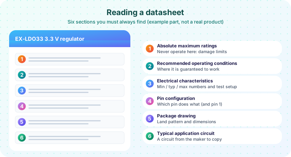
Every component has a datasheet, a document written by the manufacturer that says what the part is, how to connect it and what it can take. Datasheets are dense, but a designer reads the same six sections every time. If you get used to that routine, you can judge a part in ten minutes and avoid most of the surprises that damage boards.
This lesson also covers the question that comes before the datasheet: how to choose a part in the first place, with availability, price and risk in mind.
What you will learn
- The six datasheet sections you must always read
- The difference between absolute maximum ratings and operating conditions
- How to derate voltage, current and power
- How to pick a part: availability, second sources and lifecycle
Key terms
Absolute maximum ratings: stress limits that must never be exceeded, even briefly; the part may be damaged.
Recommended operating conditions: the range in which the part works as specified.
Typical (typ), minimum (min), maximum (max): how guaranteed values are written; only min and max are guaranteed.
Derating: using a part at less than its rating to gain margin and life.
Thermal resistance (θJA): how many °C the junction rises above ambient for each watt dissipated.
The six sections
1. Absolute maximum ratings. Supply voltage limit, pin voltage limit, storage temperature, sometimes ESD. These are the cliff edges. A 3.3 V microcontroller whose pins are rated to 3.6 V will not survive a 5 V signal. Never design to the maximums; design to the next section.
2. Recommended operating conditions. The supply range, temperature range and clock limits where the specs apply. A chip may survive 6 V but only work correctly from 1.8 V to 3.6 V. Stay inside this range everywhere on your board, including during start-up and with component tolerances.
3. Electrical characteristics. A big table of specifications with conditions: output voltage accuracy, quiet current, dropout, input thresholds, timing. Read the test conditions column. A value quoted "at 25 °C, 1 mA load" does not apply to your 85 °C, 500 mA case. Use min or max for worst-case design, never typ.
4. Pin configuration. The pinout and pin functions. This is the information you check against the schematic symbol. Note pin 1 and which view is shown.
5. Package drawing and land pattern. Dimensions, tolerances and the recommended footprint. This is what you compare with your footprint (Lesson: Footprints and Land Patterns). Also note the thermal pad, solder paste advice and the maximum soldering temperature.
6. Typical application circuit. The maker shows a working example: which capacitors, what values and where to place them. Copy it first, vary it later. Layout hints often appear in a "PCB layout guidelines" subsection and are worth following exactly, especially for switching regulators.
Other useful sections: block diagram, functional description, register map for digital chips and thermal information.
Derating and margin
Designers do not run parts at their limits. A few common habits:
- Voltage: keep ceramic capacitors at 50 % of the rated voltage or less, and other parts below about 80 % of their rating. A 25 V capacitor on a 12 V rail is a good choice; a 16 V part on 12 V is not much margin once you consider spikes.
- Power: keep resistors at 50 % or less of their power rating at the operating temperature.
- Current: keep connectors and traces at 70 to 80 % of the rated current, and check temperature rise.
- Temperature: compute junction temperature (see below) and keep it well under the limit, such as 105 or 125 °C.
The thermal calculation for a linear regulator is a classic example. The regulator turns the difference between input and output into heat: P = (Vin − Vout) × I. The die temperature is Tj = Tambient + P × θJA. Datasheet θJA values assume a specific test board; real boards with a large copper area perform better and cramped ones worse.
Choosing a part
Datasheet knowledge is only half of choosing. The other half is supply.
- Availability. Check stock at several distributors and the lead time. A perfect part that is out of stock for 52 weeks is a bad part.
- Lifecycle. Look for "active" status; avoid "not recommended for new designs" (NRND) or "obsolete".
- Second sources. Prefer parts with pin-compatible alternatives from other makers; this protects you from shortages.
- Price in volume. A 20-cent difference matters at a million units and not at ten.
- Library quality. If the manufacturer or distributor provides a symbol and footprint, you still have to check them, but it saves time.
- Hand or machine? Small packages like 0201 or BGA are fine for assembly services but a poor choice for a student kit.
For passives, pick one or two "standard" values and sizes and use them everywhere: for example, 0603 resistors at 1 % and 0603 100 nF X7R capacitors rated 16 V or more. A short list simplifies buying, assembly and inventory.
Common misconceptions
"The typical value is what I will get." Typical is an average of tested samples. Only min and max are guaranteed.
"If it is within absolute maximum ratings it is safe." Operating at the maximum may damage the part over time and the specifications are not guaranteed. Stay within recommended operating conditions.
"Any part with the same value will do." A 100 nF capacitor can be C0G, X7R or Y5V, 6.3 V or 50 V. Specify the details.
Try it
The first example picks capacitors for a rail by derating. Edit the rail voltage or the derating rule and see which candidates pass.
Press Run (or Ctrl + Enter) to see the result here.
Program input · what you'd type while the program runs
Type the answers before you press Run, one per line. Each time the program reads a line (with input()), it gets the next line from this box.
The second example computes the junction temperature of a linear regulator. The numbers are an example; use the values from your own part's datasheet.
Press Run (or Ctrl + Enter) to see the console output here.
No output.
Check your understanding
Quick check · 5 questions
of 5 answered You scored / 5 · perfect!
-
1. Which datasheet section lists limits that must never be exceeded?
Exceeding absolute maximum ratings can destroy the part. -
2. Which value in the electrical characteristics table is guaranteed?
Typical values are not guaranteed. -
3. A regulator drops 12 V to 3.3 V at 0.2 A. How much power becomes heat?
(12 − 3.3) × 0.2 = 1.74 W. -
4. A 5 V rail: which ceramic capacitor rating is a sensible choice with a 50 % rule?
5 V ÷ 0.5 = 10 V. -
5. Why prefer parts with second sources?
Supply shortages are a major risk.
Summary
- Read six sections: absolute maximums, operating conditions, electrical characteristics, pinout, package and application circuit.
- Design with min and max values and with margin, not at the limits.
- Derate voltage, power and temperature.
- Choose parts for availability, lifecycle and second sources as well as specs.
Next: Chapter 3 Review
Track your progress
Create a free account to tick off lessons and pick up where you left off on any device.
of PCB Design and Prototyping lessons completed