


















Lesson 7 of 45 · From Schematic to Board
Schematic Capture
Learn how to draw a clear schematic: symbols, reference designators, values, net labels and power symbols, with an LED resistor calculation as a worked example.
Schematic capture means drawing the circuit in software. It looks like drawing, but each symbol you place carries data: a name, a value and a link to a footprint. The wires you draw become the netlist that the layout tool will use. A good schematic is also documentation. Someone who has never seen your circuit, possibly you in a year, should be able to read it from left to right and understand it.
What you will learn
- What a symbol, a reference designator and a value are
- How wires, net labels and power symbols create connections
- How to lay out a readable sheet
- How to choose a current-limiting resistor for an LED
Key terms
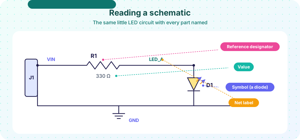
Symbol: the drawing of a part in a schematic (a zigzag or rectangle for a resistor).
Reference designator: the unique name of a part: R for resistor, C capacitor, D diode, Q transistor, U integrated circuit, J connector, L inductor, SW switch.
Net: a set of pins that are connected together, with a name such as GND or LED_A.
Net label: a name attached to a wire; wires with the same label are connected even if no line joins them.
Power symbol: a special symbol (GND, +5V, +3V3) that names a net globally.
Symbols, designators and values
Every part you place has three important fields. The reference designator (R1, C3, U2) must be unique, because it appears on the silkscreen and in the BOM. Use the standard letter prefixes: R for resistors, C for capacitors, L for inductors, D for diodes and LEDs, Q for transistors, U for integrated circuits, J for connectors, SW for switches and Y for crystals. Many tools auto-number them for you with an "annotate" command.
The value says what the part is: 330R, 100nF, LM358. Write values the way you would say them. Many designers use the letter as the decimal point (4k7 for 4.7 kΩ, 2u2 for 2.2 µF) because a dot can vanish on a printout.
The footprint field links the symbol to a pad pattern. You can assign it in the schematic or later. Either way, every symbol needs one before you update the board. Chapter 3 is entirely about footprints.
Wires, labels and power symbols
A wire joins pins that are touched by its ends. When two wires cross, they are connected only if there is a junction dot; a plain crossing means nothing. This is a classic source of mistakes, so check junction dots.
Long wires turn a schematic into spaghetti. Use net labels instead: give a short stub a name such as SDA, and place the same name at the other end. The tool treats them as one net. Power symbols work the same way, but globally: every GND symbol in the project is the same net.
For power nets, there is a second rule. Power inputs of ICs must be driven by something that the checker recognises as a source. KiCad uses PWR_FLAG symbols to say "this net is powered by an external supply", which silences a warning that nothing drives it.
Drawing a readable sheet
Good layout makes errors obvious. Follow these habits:
- Flow signals from left to right: inputs on the left, outputs on the right.
- Put power at the top and ground at the bottom. Draw positive supply rails upward and ground downward.
- Group by function: power supply in one block, microcontroller in another, sensor in a third. Use sheet titles or boxes with a caption.
- Show pin names and numbers on ICs. You will check them against the datasheet later.
- Put the decoupling capacitor next to the power pin it serves in the schematic too; it shows intent.
- Use sheets (hierarchical or multiple pages) for big designs, but keep each page readable on a screen.
Worked example: an LED and its resistor
An LED needs a resistor in series to set its current. Use Ohm's law on the resistor: R = (Vsupply − Vf) / I, where Vf is the LED's forward voltage and I the chosen current.
Take a 5 V supply, a red LED with Vf about 2.0 V (check the datasheet; it varies from about 1.8 V to 2.2 V for red) and a target current of 10 mA. Then R = (5 − 2.0) / 0.010 = 300 Ω. The nearest standard value in the E12 series is 330 Ω. The actual current is (5 − 2.0)/330 = 9.1 mA, which is fine. The resistor dissipates I² × R = 0.0091² × 330 = 27 mW, well below the 100 mW rating of a 0603 chip resistor.
Notice the logic: choose a current first, calculate, round to a standard value, and check the power. You will repeat this on almost every circuit.
Common misconceptions
"Two wires that cross are connected." Only a junction dot connects them. Always zoom in and check.
"The schematic doesn't need to be pretty because only the layout is manufactured." The schematic is how you and your reviewers find mistakes. A messy sheet hides bugs.
"Values do not matter until the BOM." Wrong values copy straight into the BOM and onto the factory floor. Fill them in as you go.
Try it
The first example calculates the resistor for several supply voltages and rounds to the nearest E12 value. This is the core of the worked example, so change the LED voltage and current and see what happens.
Press Run (or Ctrl + Enter) to see the result here.
Program input · what you'd type while the program runs
Type the answers before you press Run, one per line. Each time the program reads a line (with input()), it gets the next line from this box.
The second example is a miniature electrical rules check. It reads a list of connections and reports nets with a single pin, which are usually forgotten wires.
Press Run (or Ctrl + Enter) to see the console output here.
No output.
Check your understanding
Quick check · 5 questions
of 5 answered You scored / 5 · perfect!
-
1. Which designator letter is used for an integrated circuit?
U is the standard prefix for ICs; C is a capacitor. -
2. Two wires cross on a schematic with no dot. They are
A junction dot is needed to connect crossing wires. -
3. What do two net labels with the same name do?
Same-name labels belong to one net. -
4. 5 V supply, LED Vf = 2 V, target 10 mA. What resistor value is calculated before rounding?
(5 − 2) / 0.010 = 300 Ω; round to 330 Ω from E12. -
5. What is a PWR_FLAG for?
It tells the checker that the power net has a source.
Summary
- Each symbol has a reference designator, a value and a footprint.
- Wires join pins; labels and power symbols connect nets without lines.
- A readable layout flows left to right, power on top, ground below.
- LED resistor:
R = (Vsupply − Vf)/I, then round to a standard value and check power.
Track your progress
Create a free account to tick off lessons and pick up where you left off on any device.
of PCB Design and Prototyping lessons completed