


















Lesson 29 of 46 · Semiconductors and Metals
The Hall effect, mobility and conductivity
Understand the Hall effect in metals and semiconductors: derive R_H = -1/(ne), compute Hall voltage, extract carrier density and mobility, and handle two carrier types.
Conductivity alone cannot tell you how many carriers a material has, or whether they are electrons or holes: a few fast carriers and many slow carriers can give the same σ. Edwin Hall discovered in 1879 that a magnetic field adds a second, independent measurement. Together the two give the carrier density, the sign of the charge and the mobility. The Hall effect is one of the standard characterization tools in every semiconductor lab, and it is also the origin of the quantum Hall effect you will meet in chapter 8.
What you will learn
- How to derive the Hall coefficient R_H = 1/(nq) from force balance.
- How to compute a Hall voltage and extract n from it.
- How mobility and conductivity are related, σ = e(nμ_n + pμ_p).
- What happens when both electrons and holes contribute.
Key terms
Mobility μ: the drift velocity per unit electric field, v_d = μE. Units: m²/(V·s) or cm²/(V·s).
Hall voltage V_H: the transverse voltage across a current-carrying conductor in a perpendicular magnetic field.
Hall coefficient R_H: V_H t / (I B) = 1/(nq), where t is the sample thickness along B.
Drift velocity v_d: the average velocity of carriers under an electric field.
Force balance
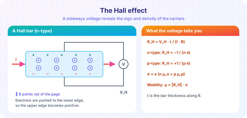
Let a current I flow along x through a bar of width w and thickness t, in a magnetic field B along z (perpendicular to the bar's broad face). Carriers with charge q and drift velocity v_d feel the Lorentz force F = q v_d × B along ±y. Charge accumulates on one edge until a transverse electric field E_H builds up that cancels it: q E_H = q v_d B, so E_H = v_d B. The current density is j = n q v_d, so v_d = j/(nq) and
E_H = j B / (n q) which gives R_H = E_H / (j B) = 1 / (n q)
The Hall voltage across the width w is V_H = E_H w = I B / (n q t) (using j = I/(wt)). Two consequences:
- The sign of V_H tells the sign of the carriers. For electrons, R_H = −1/(ne) < 0; for holes R_H = +1/(pe) > 0.
- Measuring V_H, I, B and t gives n = I B / (e t V_H). Nothing else is needed.
Example 1 (copper). n = 8.5 × 10²⁸ m⁻³, I = 1 mA, B = 0.5 T, t = 0.5 mm: V_H = I B/(n e t) = 5 × 10⁻⁴ / (8.5 × 10²⁸ × 1.602 × 10⁻¹⁹ × 5 × 10⁻⁴) ≈ 7 × 10⁻¹¹ V. That is 70 picovolts: hard to measure in a metal. Example 2 (doped silicon). n = 10²² m⁻³ (10¹⁶ cm⁻³): V_H = 5 × 10⁻⁴ / (10²² × 1.602 × 10⁻¹⁹ × 5 × 10⁻⁴) ≈ 0.62 mV. A semiconductor has far fewer carriers, so a far larger Hall signal. That is why Hall sensors in cars and phones use semiconductors.
Mobility and conductivity
Without a magnetic field, the Drude picture gives v_d = (eτ/m*) E with scattering time τ, so mobility μ = eτ/m*. Conductivity is the sum over carrier types:
σ = e (n μ_n + p μ_p)
For n-type silicon, N_D = 10¹⁶ cm⁻³ and μ_n ≈ 1350 cm²/(V·s) at low doping, σ ≈ 2.2 S/cm. Combining the two measurements gives the Hall mobility μ_H = |R_H| σ, which for a single carrier type equals the drift mobility up to a factor of order one that depends on the scattering mechanism. Mobility falls at high temperature (phonon scattering, μ ∝ T^(−3/2) in silicon) and at high doping (ionized impurity scattering). Typical room-temperature mobilities: Si electrons 1400, Si holes 450, GaAs electrons 8500, Ge electrons 3900, graphene on a substrate 10⁴ or more cm²/(V·s).
Two carrier types
When both electrons and holes matter (an intrinsic semiconductor, or a semimetal) the Hall coefficient in the weak-field limit is
R_H = (p μ_p² − n μ_n²) / ( e (p μ_p + n μ_n)² )
The sign now depends on which carrier is more mobile and more numerous: the Hall voltage reverses sign when p μ_p² = n μ_n². In an intrinsic silicon crystal, n = p and electrons are three times more mobile than holes, so R_H is negative even though the numbers are equal. Some metals (for example beryllium and zinc) have a positive Hall coefficient, evidence that their conduction involves hole-like orbits; a free electron model cannot explain this, but a full band structure can.
Common misconceptions
"A positive Hall coefficient means that positive charges move through the lattice." Holes are a convenient description of missing electrons in an almost full band; what R_H > 0 tells you is that the effective carrier near the Fermi level has positive effective mass in the transverse response.
"The Hall voltage depends on the width of the bar." For fixed current I, V_H = IB/(nqt) depends on the thickness t along the field, not the width. A thinner sample gives a larger Hall voltage.
"Mobility is the same as conductivity." Mobility is conductivity per carrier per charge. Two samples with equal σ can have very different n and μ.
Try it
Press Run (or Ctrl + Enter) to see the result here.
Program input · what you'd type while the program runs
Type the answers before you press Run, one per line. Each time the program reads a line (with input()), it gets the next line from this box.
Press Run (or Ctrl + Enter) to see the result here.
Program input · what you'd type while the program runs
Type the answers before you press Run, one per line. Each time the program reads a line (with input()), it gets the next line from this box.
Check your understanding
Quick check · 5 questions
of 5 answered You scored / 5 · perfect!
-
1. The Hall coefficient of a single carrier type with density n and charge q is
Force balance gives E_H = jB/(nq), so R_H = E_H/(jB) = 1/(nq). -
2. A Hall voltage has the polarity opposite to the one electrons would give in the same geometry. The carriers are most likely
The sign of V_H follows the sign of the charge; the opposite polarity to the electron case means positive carriers. -
3. Why do Hall sensors use semiconductors rather than copper?
V_H ∝ 1/n; copper's 10²⁸–10²⁹ m⁻³ gives picovolt signals. -
4. Conductivity of a semiconductor with both carrier types is
Electrons and holes both carry current in the direction of the field, so their contributions add. -
5. The Hall mobility is computed as
μ = σ/(ne) and |R_H| = 1/(ne) give μ_H = |R_H| σ.
Summary
- Force balance in crossed fields gives R_H = V_H t/(IB) = 1/(nq): the sign and the density of the carriers.
- Conductivity σ = e(nμ_n + pμ_p); the Hall mobility is |R_H|σ.
- Two carrier types give R_H = (pμ_p² − nμ_n²)/(e(pμ_p + nμ_n)²), which can change sign.
- Semiconductors give large Hall voltages because their carrier density is low.
Next: Chapter review
Track your progress
Create a free account to tick off lessons and pick up where you left off on any device.
of Condensed Matter Physics lessons completed