


















Lesson 12 of 45 · Transformers
The Ideal Transformer
Learn the ideal transformer: the EMF equation E = 4.44 f N Phi, turns ratio, current ratio, impedance reflection, polarity dots, and worked examples with numbers.
Before dealing with the imperfections of real transformers, build a perfect one in your head. The ideal transformer follows a handful of exact rules. Real transformers obey them to within a few percent, so the ideal model is not just a teaching toy: it is the first design estimate and the core of every more detailed model that follows.
What you will learn
- The four assumptions that define an ideal transformer.
- How the EMF equation
E = 4.44 f N Φmarises. - How to apply the turns ratio to voltage, current and impedance.
- How polarity dots show the relative direction of the voltages.
Key terms
Ideal transformer: zero winding resistance, no leakage flux, infinite core permeability and no core loss.
EMF equation: E_rms = 4.44 f N Φm, with Φm the peak core flux.
Turns ratio a: a = N1 / N2.
Reflected (referred) impedance: a load impedance as seen from the other winding.
Polarity dots: marks showing which ends of the two windings are positive at the same instant.
The four assumptions
- The windings have no resistance, so there is no
I²Rloss and no voltage drop. - All flux stays in the core and links both windings: no leakage flux.
- The core has infinite permeability, so it takes no MMF to establish the flux: no magnetizing current.
- There is no hysteresis or eddy-current loss.
The EMF equation
Let the core flux be sinusoidal, Φ = Φm sin(ωt). The voltage induced in a winding of N turns is:
e = N dΦ/dt = N ω Φm cos(ωt)
So the induced voltage leads the flux by 90° and has peak Em = N ω Φm = 2π f N Φm. The RMS value is the peak divided by √2:
E_rms = (2π / √2) f N Φm = 4.44 × f × N × Φm
With Φm = Bm × A_core this becomes E = 4.44 f N Bm A. In the ideal transformer the terminal voltage equals the induced voltage in each winding.
Worked example: sizing a core. Design a 230 V, 50 Hz primary on a core of 50 cm² area with peak flux density Bm = 1.4 T.
Φm = 1.4 × 50×10⁻⁴ = 7.0×10⁻³ Wb.- Volts per turn:
E/N = 4.44 × 50 × 7.0×10⁻³ = 1.554 V/turn. - Primary turns:
N1 = 230 / 1.554 = 148. - A 24 V secondary needs
24 / 1.554 ≈ 15turns.
The "volts per turn" figure is how designers think: it depends only on frequency and core size, not on the voltage rating.
Voltage, current, impedance
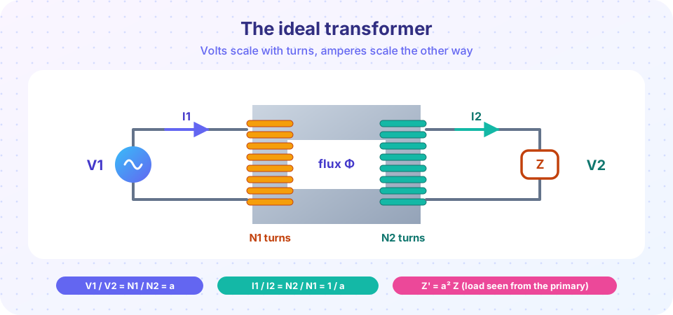
Because the same flux links both windings, the induced voltage per turn is the same:
E1 / N1 = E2 / N2 → V1 / V2 = N1 / N2 = a
With no losses, input power equals output power, V1 I1 = V2 I2, so:
I1 / I2 = N2 / N1 = 1 / a
A step-down transformer (a > 1) has the larger current on the low-voltage side.
Impedance reflection
A load Z2 = V2 / I2 on the secondary looks, from the primary, like:
Z1' = V1 / I1 = (a V2) / (I2 / a) = a² Z2
The impedance is scaled by the square of the turns ratio. Engineers use this to match loads: a transformer with a = 10 makes an 8 Ω speaker look like 800 Ω to the amplifier.
Worked example. A 10 kVA, 2000 V / 200 V transformer (a = 10) feeds a 4 Ω load at 200 V.
- Secondary current:
I2 = 200 / 4 = 50 A(power10 kW). - Primary current:
I1 = I2 / a = 5 A. - Reflected load:
Z1' = 10² × 4 = 400 Ω, andV1 / Z1' = 2000/400 = 5 A, which agrees.
Rated values
The ratings of a transformer are its voltages and its apparent power in kVA, not in kW: the transformer does not know the power factor of the load, and both winding currents are limited by heating. The 10 kVA transformer above has a rated primary current of 10 000 / 2000 = 5 A and a rated secondary current of 50 A, whatever the load.
Polarity dots
Two windings can be connected so their voltages add or subtract, so the winding ends are marked with dots. Rule: current entering the dotted end of one winding produces a voltage that makes the dotted end of the other winding positive. With the dot convention, V2 is in phase with V1 for the ideal transformer (not 180° out of phase), and I1 flows into the primary dot while I2 flows out of the secondary dot. Polarity matters when connecting transformers in parallel or in three-phase banks: a wrong polarity connection produces a short circuit.
Common misconceptions
"The transformer ratio applies to power too." Ratios apply to voltage and current; power is the same on both sides (ideal) or slightly smaller on the output (real).
"Impedance scales with a." It scales with a²: Z1' = a² Z2.
"Rating a transformer in kW is fine." The standard is kVA, because the limits are voltage and current.
Try it
Press Run (or Ctrl + Enter) to see the result here.
Program input · what you'd type while the program runs
Type the answers before you press Run, one per line. Each time the program reads a line (with input()), it gets the next line from this box.
Press Run (or Ctrl + Enter) to see the result here.
Program input · what you'd type while the program runs
Type the answers before you press Run, one per line. Each time the program reads a line (with input()), it gets the next line from this box.
Check your understanding
Quick check · 5 questions
of 5 answered You scored / 5 · perfect!
-
1. An ideal transformer has N1 = 600 and N2 = 150. The primary voltage is 240 V. What is the secondary voltage?
V2 = V1 N2/N1 = 240 × 150/600 = 60 V. -
2. The secondary of that transformer carries 8 A. What is the primary current?
I1 = I2 N2/N1 = 8 × 150/600 = 2 A. -
3. A 2 Ω load on the secondary of a transformer with a = 5 appears to the primary as:
Z1' = a² Z2 = 25 × 2 = 50 Ω. -
4. What is the RMS emf of a 100-turn winding with a peak flux of 5 mWb at 60 Hz?
E = 4.44 × 60 × 100 × 0.005 = 133 V. -
5. Why are transformers rated in kVA rather than kW?
Winding heating depends on current and insulation stress on voltage, not on the power factor of the load.
Summary
- An ideal transformer has no resistance, no leakage, infinite permeability and no core loss.
E = 4.44 f N Φm; volts per turn depends only on frequency and core flux.V1/V2 = N1/N2 = a,I1/I2 = 1/a,Z1' = a² Z2; power is the same on both sides.- Ratings are in kVA; polarity dots show which ends are positive together.
Track your progress
Create a free account to tick off lessons and pick up where you left off on any device.
of Electrical Machines lessons completed