


















Lesson 13 of 45 · Transformers
The Equivalent Circuit of a Real Transformer
Build the equivalent circuit of a real transformer: winding resistance, leakage reactance, core loss and magnetizing branch, referring to one side, with worked numbers.
A real transformer departs from the ideal in four ways, and each one has a circuit element to represent it. Add them to the ideal transformer and you get an equivalent circuit: a network of resistors and inductors that predicts the terminal voltages, the currents and the losses with an accuracy of a fraction of a percent. This is your first example of a modeling technique that the induction motor and the synchronous generator will reuse.
What you will learn
- What physical effect each element of the circuit represents.
- How to refer secondary quantities to the primary.
- Why the no-load current is not sinusoidal and what inrush current is.
- How to compute the terminal voltage under load with the approximate circuit.
Key terms
Leakage flux: flux that links only one winding. It acts like a small series inductance, giving the leakage reactances X1 and X2.
Magnetizing current (Iφ): the current that creates the core flux; it has a loss component Ic and a reactive component Im.
Referred quantity: a quantity from one winding converted to the other side by the turns ratio.
Equivalent impedance: Z_eq = R_eq + j X_eq, the series impedance of both windings seen from one side.
Inrush current: the large transient current when a transformer is switched on.
The four imperfections
- Winding resistance
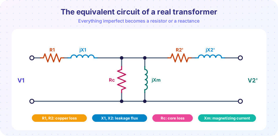
R1,R2. The copper has resistance, givingI²Rloss and a voltage drop. Series resistors. - Leakage flux. Some flux of each winding does not link the other. It stores energy and behaves like a series inductance, represented by
X1andX2. It is the main reason the secondary voltage falls under load. - Core loss. Hysteresis and eddy currents dissipate
P_c = V1² / Rcat rated voltage. A shunt resistorRcacross the supply represents it. - Finite permeability. Even a good core needs some current to set up the flux, called the magnetizing current. A shunt reactance
Xmrepresents it.
The shunt branch Rc ∥ Xm carries the no-load current I0, usually only 1 to 5 percent of rated current in power transformers. Its two components are:
Ic = V1 / Rc   (in phase with V1: core loss)
Im = V1 / Xm   (lags V1 by 90°: magnetizing)
I0 = √(Ic² + Im²)
Referring to the primary
The exact model has the real secondary in series with an ideal transformer. To avoid carrying the ratio through every calculation, refer everything to one side. Moving from the secondary to the primary side with a = N1/N2:
V2' = a V2          I2' = I2 / a
R2' = a² R2         X2' = a² X2         Z_L' = a² Z_L
The resulting circuit (the picture) has no transformer in it. Once solved, convert back with the inverse relations.
The approximate circuit
Since I0 is tiny compared with the load current, move the shunt branch to the input terminals. The series elements merge:
R_eq = R1 + R2' X_eq = X1 + X2'
This approximate circuit is accurate enough for almost all power-system work.
Worked example: a 10 kVA, 2000/200 V transformer
A 10 kVA, 2000/200 V, 50 Hz transformer has (referred to the primary) R1 = 2.4 Ω, R2' = 2.4 Ω, X1 = 7.63 Ω, X2' = 7.63 Ω, Rc = 44.4 kΩ and Xm = 18.0 kΩ. These come from the tests in the next lesson.
- Equivalent impedance:
R_eq = 4.8 Ω,X_eq = 15.26 Ω,|Z_eq| = 16.0 Ω. - Rated primary current:
10 000 / 2000 = 5 A. - Rated voltage drop in
Z_eq:5 × 16.0 = 80 V, which is4 %of 2000 V. - No-load current:
Ic = 2000 / 44 400 = 0.045 A,Im = 2000 / 18 000 = 0.111 A,I0 = 0.12 A, which is2.4 %of rated current.
Terminal voltage under load
The supply is V1 = 2000 V. The load takes rated current at power factor 0.8 lagging. In the approximate circuit V1 = V2' + I' Z_eq with I' = 5∠-36.87° A. Writing I' Z_eq = 80 ∠35.67° = 65.0 + j46.7 V and solving for the magnitude of V2' that gives |V1| = 2000 V yields V2' = 1934.5 V, so V2 = 193.4 V: about 3.3 percent below the 200 V no-load value. This voltage fall is the voltage regulation problem treated in the next lesson.
Note the effect of power factor: a lagging load makes both the resistive and reactive drops subtract from V2. A leading (capacitive) load can even raise V2 above its no-load value, because the reactive drop then reverses sign.
The magnetizing current is not a sine wave
Because iron saturates, the current needed to set up a sinusoidal flux is not sinusoidal. When the flux peaks, the iron is near the knee, and a disproportionate current is needed. The current waveform is peaked and contains a strong third harmonic. At higher flux density the effect is stronger, so designers keep the working flux below the knee. In a three-phase system the third harmonics have special effects on the connections (next lesson).
Inrush current
Switch a transformer on at the moment when the supply voltage is zero, and the flux has to rise from zero toward twice its normal peak, plus any residual flux left from the last switch-off. The iron saturates deeply and the primary draws a very large, decaying, harmonic-rich current. Typical values are several to ten times rated current, lasting a few cycles. Protection relays are designed not to trip on inrush.
Common misconceptions
"The no-load current is small, so the shunt branch can be ignored in every calculation." For regulation and load calculations yes, but the shunt branch determines the core loss and the efficiency at light load.
"Leakage flux is a defect of poor manufacturing only." Some leakage is unavoidable; it is even exploited (in welding transformers) to limit the short-circuit current.
"Referred values are the real values." They are calculation aids. The real secondary resistance is R2'/a².
Try it
Press Run (or Ctrl + Enter) to see the result here.
Program input · what you'd type while the program runs
Type the answers before you press Run, one per line. Each time the program reads a line (with input()), it gets the next line from this box.
Press Run (or Ctrl + Enter) to see the result here.
Program input · what you'd type while the program runs
Type the answers before you press Run, one per line. Each time the program reads a line (with input()), it gets the next line from this box.
Check your understanding
Quick check · 5 questions
of 5 answered You scored / 5 · perfect!
-
1. Which circuit element represents the core (iron) loss?
Core loss is V²/Rc, produced by a resistor in parallel with the supply (the shunt branch). -
2. A transformer has a = 10 and R2 = 0.05 Ω. What is R2' referred to the primary?
R2' = a² R2 = 100 × 0.05 = 5 Ω. -
3. Why is the no-load current of a real transformer not sinusoidal?
The B-H curve is nonlinear; near the knee small increases of flux need much larger currents. -
4. Which effect causes most of the voltage fall of the secondary under inductive load?
The series impedance R_eq + jX_eq carries the load current and drops voltage. -
5. Ic = 0.05 A and Im = 0.12 A. What is the no-load current I0?
I0 = √(0.05² + 0.12²) = √0.0169 = 0.13 A (the components are 90° apart).
Summary
- The equivalent circuit has series
R1, X1, R2', X2'and a shunt branchRc ∥ Xm. - Referring to the primary multiplies secondary impedances by
a², voltages byaand divides currents bya. - The approximate circuit shifts the shunt branch to the input:
R_eq = R1 + R2',X_eq = X1 + X2'. - Magnetizing current is peaky (third harmonic) because of saturation; inrush current can reach several times the rated current.
Track your progress
Create a free account to tick off lessons and pick up where you left off on any device.
of Electrical Machines lessons completed