


















Lesson 38 of 45 · Efficiency, Testing and Applications
Testing motors and transformers
Find the equivalent circuit of an induction motor from the DC, no-load and blocked-rotor tests and of a transformer from open-circuit and short-circuit tests, with worked numbers.
You cannot open a sealed motor and measure its leakage reactance with a ruler. Fortunately you do not need to. Two simple tests, one with the shaft free and one with the shaft locked, give you every parameter of the equivalent circuit. Transformers have a matching pair: an open-circuit and a short-circuit test. Together they cost almost no energy, because the tests run either at no load or at reduced voltage.
This lesson shows how each test works, what the meters read, and how to turn the readings into circuit values and predictions.
What you will learn
- How the DC, no-load and blocked-rotor tests give
R1,Xm, the core and friction loss, and the leakage values. - How the open-circuit and short-circuit tests give a transformer's equivalent circuit.
- How to use the results to predict efficiency and voltage regulation.
- How alternator open-circuit and short-circuit tests find the synchronous reactance.
Key terms
No-load test: the motor runs at rated voltage with no mechanical load; the current is almost entirely magnetizing.
Blocked-rotor (locked-rotor) test: the rotor is held still and a reduced voltage drives rated current through the windings.
Open-circuit (OC) test: rated voltage on one transformer winding, the other open.
Short-circuit (SC) test: reduced voltage on one winding, the other shorted, to circulate rated current.
Equivalent impedance Zeq: the transformer's series impedance referred to one side.
Testing an induction motor
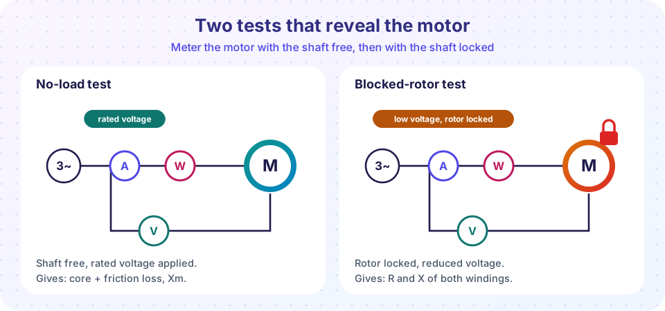
1. DC test. Apply a small DC voltage between two terminals and measure voltage and current. For a star-connected stator the resistance between two lines is 2 R1, so R1 = Vdc / (2 Idc). Correct for temperature if needed.
2. No-load test. The motor runs at rated voltage with the shaft free, so the slip is tiny and the rotor branch carries almost no current. The meters read the line voltage V0, the current I0 (typically 25 % to 50 % of rated for small motors and less for large ones) and the three-phase power P0. The power covers the core loss, the friction and windage loss, and a small stator copper loss 3 I0² R1, so
Pcore + Pfw = P0 − 3 I0² R1
Z0 = (V0 / √3) / I0      R0 = P0 / (3 I0²)      X0 = √(Z0² − R0²)      Xm ≈ X0 − X1
To split the core loss from the friction loss, repeat the test at several lower voltages and plot P0 − 3 I0² R1 against V². Core loss goes with V² and friction does not, so the straight line extrapolated to V = 0 gives the friction and windage loss.
3. Blocked-rotor test. Lock the rotor and raise the voltage from zero until the current reaches the rated value. This takes only 10 % to 25 % of rated voltage, so the flux and the magnetizing current are small and the magnetizing branch can be ignored. Then
Zbr = (Vbr / √3) / Ibr Rbr = Pbr / (3 Ibr²) = R1 + R2' Xbr = √(Zbr² − Rbr²) = X1 + X2'
with R2' = Rbr − R1. The split of Xbr between X1 and X2' cannot be measured; a common rule (from the motor design class) is half and half for general-purpose motors. Standards ask for the blocked-rotor test at a reduced frequency, because the rotor reactance at a running slip is lower than at standstill; the simple version above is fine for a first estimate.
A worked example
A 400 V, 4-pole, 50 Hz, star-connected motor gives these readings: DC test between two terminals 0.70 Ω; no-load 400 V, 6.4 A, 475 W; blocked rotor 76 V, 22.9 A, 1020 W. The program below finds R1 = 0.35 Ω, Pcore + Pfw ≈ 432 W, Xm ≈ 35 Ω, R2' ≈ 0.30 Ω and X1 = X2' ≈ 0.90 Ω, which are the parameters of the motor used throughout this chapter.
Testing a transformer
For a single-phase transformer:
- Open-circuit test. Apply rated voltage
V0to the low-voltage winding (convenient) with the high-voltage winding open. The wattmeter reads the core lossPc(the copper loss at this tiny current is negligible). ThenRc = V0² / Pc,Ic = Pc / V0,Im = √(I0² − Ic²)andXm = V0 / Im. - Short-circuit test. Short the low-voltage winding and raise the voltage on the high-voltage winding until rated current flows, which takes about 3 % to 10 % of rated voltage. The flux is small, so the core loss is negligible and the wattmeter reads the full-load copper loss
Pcu. ThenZeq = Vsc / Isc,Req = Pcu / Isc²andXeq = √(Zeq² − Req²).
The OC result gives the fixed loss and the SC result gives the variable loss, and both are measured in conditions that need only a fraction of the rated power. For very large transformers a back-to-back (Sumpner) test also checks the temperature rise.
Alternators
The same idea works for synchronous machines. The open-circuit test records the generated EMF against field current at rated speed. The short-circuit test records the armature short-circuit current against field current. For one field current If, Zs = Voc / Isc (per phase, using the unsaturated, linear part of the curve) and Xs = √(Zs² − Ra²).
Common misconceptions
"The blocked-rotor test runs at rated voltage." It would draw 5 to 8 times the rated current and burn the winding. Only about 10 to 25 % of rated voltage is used.
"The no-load power is the core loss." It also contains friction and windage and a small copper loss.
"The transformer short-circuit test measures the core loss." It measures the copper loss; the open-circuit test measures the core loss.
Try it
Extract the circuit parameters of the induction motor from the three tests.
Press Run (or Ctrl + Enter) to see the result here.
Program input · what you'd type while the program runs
Type the answers before you press Run, one per line. Each time the program reads a line (with input()), it gets the next line from this box.
Now the transformer: a 10 kVA, 2300/230 V unit. The OC test is done on the 230 V side and the SC test on the 2300 V side. The program builds the equivalent circuit and predicts regulation and efficiency.
Press Run (or Ctrl + Enter) to see the result here.
Program input · what you'd type while the program runs
Type the answers before you press Run, one per line. Each time the program reads a line (with input()), it gets the next line from this box.
Check your understanding
Quick check · 5 questions
of 5 answered You scored / 5 · perfect!
-
1. In the no-load test of an induction motor, the wattmeter reading mainly covers
At no load the slip and the rotor current are tiny, so the input power supplies the fixed losses and a small I²R in the stator. -
2. Why is the blocked-rotor test done at a reduced voltage?
With a locked rotor the impedance is low, so a small voltage already drives rated current. -
3. A blocked-rotor test gives Rbr = 0.65 Ω. The stator resistance is R1 = 0.35 Ω. What is R2'?
Rbr = R1 + R2', so R2' = 0.65 − 0.35 = 0.30 Ω. -
4. What does the short-circuit test of a transformer measure directly?
At rated current and low voltage the core loss is negligible, so the wattmeter reads the full-load copper loss. -
5. A transformer OC test (on the LV side) gives 230 V, 65 W. The core-loss resistance Rc is about
Rc = V0² / P0 = 230² / 65 ≈ 814 Ω.
Summary
- DC test gives
R1; no-load test gives core + friction loss andXm; blocked-rotor test givesR1 + R2'andX1 + X2'. - Transformer OC test gives core loss and the magnetizing branch; SC test gives copper loss and
Zeq. - Both pairs of tests are cheap and safe because they run at no load or at reduced voltage.
- The results predict efficiency and regulation without ever loading the machine.
Next: Motor selection and duty
Track your progress
Create a free account to tick off lessons and pick up where you left off on any device.
of Electrical Machines lessons completed