


















Lesson 19 of 45 · DC Machines
DC Generators
Understand DC generators: separately excited, shunt, series and compound types, the magnetization curve, voltage build-up, terminal characteristics, regulation, losses and efficiency.
A DC generator turns mechanical power into direct-current electrical power. Although alternators with rectifiers have largely taken over, the DC generator is a perfect case study: it shows how the EMF equation, the magnetization curve of the iron and the armature resistance combine to give a terminal voltage that depends on the load.
The big question for every generator is the same: what voltage will appear at the terminals when the load current is IL? The answer depends on how the field winding is supplied.
What you will learn
- The voltage and current relations for each generator type.
- What the magnetization curve is and how a shunt generator builds up its voltage.
- How terminal characteristics and voltage regulation compare across types.
- How to compute losses and efficiency.
Key terms
Magnetization (open-circuit) characteristic: the generated EMF against field current at constant speed.
Residual flux: the small flux left in the iron at zero field current; it starts the build-up.
Critical field resistance: the largest shunt-field resistance at which a shunt generator still builds up.
Voltage regulation: (V_no-load − V_full-load) / V_full-load, expressed in percent.
Terminal voltage (Vt): the voltage available at the brushes after the internal drops.
The basic equations
For any generator, the terminal voltage is the generated EMF minus the drops in the armature circuit:
Vt = E − Ia Ra            (brush drop of 1 to 2 V is often added)
E  = K Φ ω
The load current IL, the armature current Ia and the field current If are linked by the connection:
| Type | Field connection | Currents |
|---|---|---|
| Separately excited | Own supply | Ia = IL |
| Shunt | Across the armature | Ia = IL + If, If = Vt / Rf |
| Series | In series with the load | Ia = IL = If |
| Compound | Both | Ia = IL + If_shunt (short-shunt differs slightly) |
Worked example: power flow in a shunt generator
A shunt generator delivers IL = 48 A at Vt = 220 V. Its field resistance is Rf = 110 Ω and the armature resistance Ra = 0.2 Ω.
- Field current:
If = 220 / 110 = 2 A. - Armature current:
Ia = 48 + 2 = 50 A. - Generated EMF:
E = 220 + 50 × 0.2 = 230 V. - Developed power:
E Ia = 230 × 50 = 11 500 W. - Output:
220 × 48 = 10 560 W. Armature copper loss:50² × 0.2 = 500 W. Field loss:220 × 2 = 440 W. Check:10 560 + 500 + 440 = 11 500 W. ✓
The shaft must supply 11 500 W plus the friction, windage and iron losses.
The magnetization curve and build-up
At constant speed, E is proportional to the flux Φ, and so (through the iron) to the field current If, but not linearly: at low If it rises steeply, then bends over as the iron saturates. Even at If = 0 there is a small voltage Er because of residual flux.
A shunt generator has no separate supply for its field. It builds up as follows:
- Residual flux induces a small EMF
Er(a few volts) as the armature turns. - This voltage drives a small current through the field winding.
- If the field is connected so that this current adds to the residual flux, the flux grows, the EMF grows, the field current grows...
- The process stops at the intersection of the magnetization curve with the field resistance line
V = If Rf, which is the operating point.
A larger Rf gives a steeper line and a lower final voltage. If the line is steeper than the initial slope of the magnetization curve, the line and the curve only meet near zero and the generator does not build up. That limit is the critical field resistance. Failure to build up can also be caused by lost residual flux (restore it by briefly flashing the field from a battery), reversed field connection, or too low a speed (below the critical speed).
Terminal characteristics
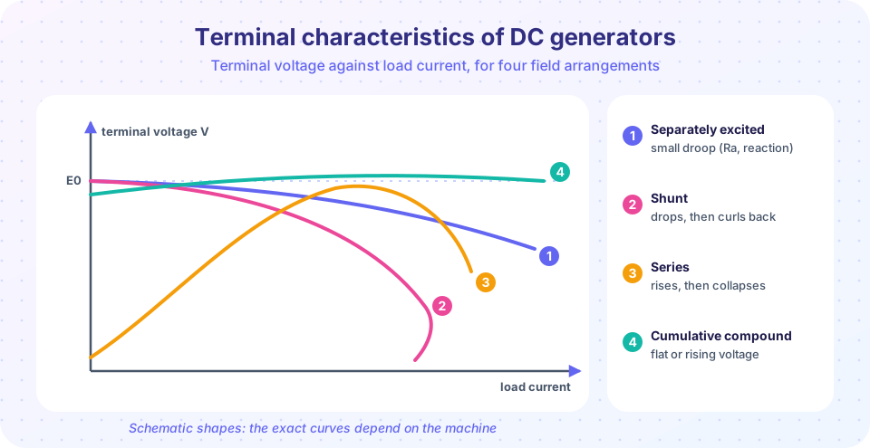
Plot Vt against IL at constant speed.
- Separately excited: the voltage falls only a little with load, because of
Ia Raand the demagnetizing armature reaction (typical drop 5 to 10 %). - Shunt: drops more, because the falling terminal voltage also reduces
If, which reducesE. At large overload the voltage collapses and the current actually decreases (the curve turns back). - Series: at light load the voltage is low (the field is weak); then it rises with load as the field strengthens, and falls again when the iron saturates. Used rarely, for series arc lighting and boosters.
- Compound: a series field, aiding the shunt field (cumulative), compensates the drop. Flat-compounded has the same voltage at no load and full load; over-compounded rises with load; a differential winding gives a sharply falling characteristic (useful for welding).
Voltage regulation: (V_nl − V_fl) / V_fl × 100 %. A small value means a stiff supply.
Losses and efficiency
| Loss | Cause | Behavior |
|---|---|---|
| Armature copper | Ia² Ra |
Varies with load |
| Field copper | If² Rf or Vt If |
Roughly constant in shunt machines |
| Iron (core) | Hysteresis and eddy currents in armature iron | Roughly constant |
| Mechanical | Friction (bearings, brushes) and windage | Roughly constant at constant speed |
| Brush contact | Vb Ia |
Varies with load |
| Stray | Miscellaneous | Small |
η = Pout / (Pout + losses), and the maximum efficiency again occurs when the variable losses equal the constant losses (chapter 1). Typical efficiencies run from about 75 % for small machines to above 90 % for large ones.
Common misconceptions
"A shunt generator always builds up." It needs residual flux, correct field polarity, a field resistance below the critical value and enough speed.
"The terminal voltage equals the generated EMF." Only at no load. Under load Vt = E − Ia Ra, and E itself also falls with armature reaction.
"Series generators are good for ordinary loads." Their voltage changes with load in the wrong way for most uses.
Try it
Press Run (or Ctrl + Enter) to see the result here.
Program input · what you'd type while the program runs
Type the answers before you press Run, one per line. Each time the program reads a line (with input()), it gets the next line from this box.
Press Run (or Ctrl + Enter) to see the result here.
Program input · what you'd type while the program runs
Type the answers before you press Run, one per line. Each time the program reads a line (with input()), it gets the next line from this box.
Check your understanding
Quick check · 5 questions
of 5 answered You scored / 5 · perfect!
-
1. A separately excited generator has E = 250 V, Ra = 0.4 Ω and delivers 40 A. What is the terminal voltage (ignore brush drop)?
Vt = E − Ia Ra = 250 − 40 × 0.4 = 234 V. -
2. A shunt generator supplies 100 A at 230 V with Rf = 115 Ω. What is the armature current?
If = 230/115 = 2 A, so Ia = IL + If = 102 A. -
3. Why does a shunt generator fail to build up if the field resistance is too high?
The critical field resistance is the slope of the straight part of the magnetization curve; steeper lines meet the curve only at low voltage. -
4. Which generator type has a voltage that rises with load?
The series field of an over-compounded generator overcompensates the armature drop. -
5. A shunt generator has 440 W field loss, 500 W armature loss and delivers 10.56 kW. What is the developed power?
Developed power = output + armature copper loss + field loss = 10 560 + 500 + 440 = 11 500 W.
Summary
Vt = E − Ia Ra; for shunt machinesIa = IL + If.- The magnetization curve plus the field-resistance line determines build-up and the no-load voltage; a critical resistance exists above which build-up fails.
- Separately excited and compound generators give a stiff voltage; shunt droops and collapses on overload; series rises then falls.
- Losses: armature and field copper, iron, mechanical, brush and stray;
P_dev = E Iaincludes everything but the mechanical and iron losses.
Track your progress
Create a free account to tick off lessons and pick up where you left off on any device.
of Electrical Machines lessons completed