


















Lesson 28 of 45 · Synchronous Machines
Alternator EMF and voltage regulation
Learn how an alternator generates voltage and frequency, draw its per-phase equivalent circuit and phasor diagram, and calculate voltage regulation for lagging, unity and leading loads.
An alternator turns mechanical power into three-phase electrical power. The turbine or engine spins the rotor, the rotor field winding carries direct current, and the rotating magnetic poles sweep across the stator conductors. Faraday's law does the rest: every conductor sees a changing flux, so a sinusoidal voltage appears.
Two questions matter in practice. How big is that voltage and what sets its frequency? And when you connect a load, how much does the terminal voltage change? The answers come from a simple per-phase circuit and one phasor diagram.
What you will learn
- The formulas for generated EMF and frequency.
- Why a machine needs a synchronous reactance and what it stands for.
- How to use the phasor diagram to find the internal voltage and the voltage regulation.
- How real and reactive power are controlled once an alternator is on the grid.
Key terms
Excitation: the direct current in the rotor field winding, which sets the rotor flux.
Synchronous reactance Xs: the combined effect of the armature leakage reactance and armature reaction, treated as one reactance per phase.
Internal voltage E: the open-circuit EMF per phase produced by the field.
Voltage regulation: (E − V) / V, the rise in terminal voltage when the full load is removed.
Armature reaction: the effect of the stator current's own magnetic field on the main field.
Generated EMF and frequency
The rms EMF induced in one phase is
E = 4.44 kw f Φ Nph
where Φ is the flux per pole in webers, Nph is the number of series turns per phase and kw is the winding factor (about 0.9 to 0.96, a number that accounts for how the coils are spread and short-pitched). The frequency follows from the speed and the number of poles:
f = P n / 120
A turbo-generator is a long, slim cylindrical-rotor machine with 2 or 4 poles that runs at 3000/3600 or 1500/1800 rpm. A hydro generator is a wide, slow salient-pole machine: at 100 rpm and 50 Hz it needs P = 120 × 50 / 100 = 60 poles. For a given machine Φ is set by the field current, so the open-circuit voltage rises with If until the iron saturates and the curve flattens.
Why a synchronous reactance?
When the stator carries current, it makes its own magnetic field. At lagging power factor that field opposes the rotor field (it weakens it), at leading power factor it helps it. On top of this the stator has leakage flux. A clean way to handle both is to model them with one reactance in series with the winding, the synchronous reactance Xs, so that the machine becomes an ideal voltage source E behind an impedance Ra + jXs:
E = V + I (Ra + jXs)
Xs is typically 1 to 2 per unit for large machines; Ra is small, a few percent of Xs.
The phasor diagram
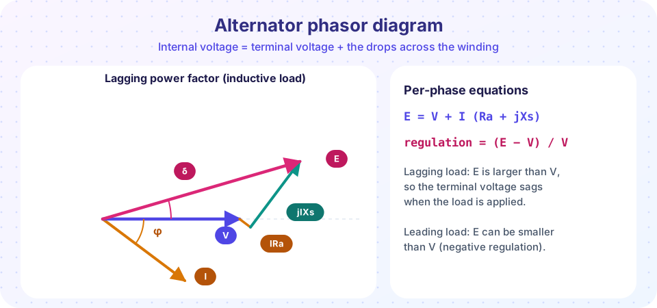
Start with the terminal voltage V along the horizontal axis. Draw I at angle φ (below the axis for a lagging load). Add I·Ra parallel to I and j I Xs at 90° ahead of I. The vector sum from the origin is E. The angle between E and V is the load angle δ, which the next lesson uses.
A worked example
A three-phase, star-connected alternator is rated 1000 kVA at 6.6 kV with Ra = 1.0 Ω and Xs = 15 Ω per phase. The phase voltage is 6600 / √3 = 3810 V and the rated current is 1 000 000 / (√3 × 6600) = 87.5 A. At rated current and 0.8 lagging:
I = 87.5∠−36.9° A, so I(Ra + jXs) = 87.5∠−36.9° × 15.03∠86.2° ≈ 1315∠49.3° V, and E = 3810 + 1315∠49.3° ≈ 4773∠12.1° V. The regulation is (4773 − 3810) / 3810 = 25 %.
The program below repeats this for three power factors. The pattern it shows is important: a lagging load needs the largest field (and gives the largest regulation), a leading load can give a negative regulation, because the armature reaction then helps the field.
Real and reactive power on the grid
Once an alternator is connected to a large grid (an "infinite bus"), the voltage and frequency are fixed by the grid. Two knobs remain:
- Prime-mover input (steam, water, fuel) sets the real power
P. Opening the valve pushes the rotor ahead and raisesδ. - Field current sets the reactive power
Q. An over-excited machine supplies lagging reactive power to the grid; an under-excited one absorbs it.
Before closing the breaker on the grid, four conditions must hold: equal voltage, equal frequency, the same phase sequence and the same phase angle. A synchroscope or an automatic synchronizer checks them. Closing the breaker with a large phase error produces a severe current surge and mechanical shock.
Common misconceptions
"The terminal voltage of an alternator is constant." It changes with load and power factor unless the excitation is regulated by an automatic voltage regulator.
"Regulation is always positive." For a sufficiently leading load the terminal voltage rises on load and the regulation is negative.
"The field current sets the active power." It sets the voltage and reactive power. Active power comes from the prime mover.
Try it
Solve the phasor equation for lagging, unity and leading loads and plot regulation against power factor.
Press Run (or Ctrl + Enter) to see the result here.
Program input · what you'd type while the program runs
Type the answers before you press Run, one per line. Each time the program reads a line (with input()), it gets the next line from this box.
Now explore the phasor diagram yourself. Move the sliders for the load current and the power-factor angle; a positive angle is lagging.
Check your understanding
Quick check · 5 questions
of 5 answered You scored / 5 · perfect!
-
1. A hydro generator runs at 125 rpm and must deliver 50 Hz. How many poles does it need?
P = 120 f / n = 120 × 50 / 125 = 48 poles. -
2. What does the synchronous reactance Xs represent?
Xs lumps the leakage flux and the demagnetizing or magnetizing effect of the armature current into one series reactance. -
3. An alternator has V = 3810 V per phase and E = 4773 V per phase at full load. The voltage regulation is about
Regulation = (E − V) / V = (4773 − 3810) / 3810 ≈ 0.25, or 25 %. -
4. For which kind of load can the regulation of an alternator be negative?
At leading power factor the armature reaction magnetizes the field, so the terminal voltage can exceed the no-load EMF. -
5. An alternator is connected to a large grid. Which action mainly changes its reactive power output?
The grid fixes voltage and frequency; the field current sets the reactive power, and the prime mover sets the real power.
Summary
E = 4.44 kw f Φ Nphandf = P n / 120.- A synchronous machine is a source
EbehindRa + jXs:E = V + I (Ra + jXs). - Regulation
(E − V) / Vis largest for lagging loads and can be negative for leading loads. - On the grid, the prime mover sets
Pand the field current setsQ.
Track your progress
Create a free account to tick off lessons and pick up where you left off on any device.
of Electrical Machines lessons completed