


















Lesson 24 of 45 · Induction Motors
Slip and the equivalent circuit
Define slip, find the rotor frequency, draw the per-phase equivalent circuit of an induction motor and follow the power from the supply to the shaft with a worked example.
An induction motor is a transformer whose secondary can turn. The stator is the primary, the rotor bars form a short-circuited secondary, and the "turning" part is what makes the circuit interesting. When the rotor is held still, the rotating field sweeps past the bars at full speed and induces a large voltage. When the rotor spins nearly as fast as the field, the bars see only a slow relative motion and the induced voltage is small.
That relative speed is captured by one number, the slip. Once you know it, you can reduce the whole motor to one small circuit per phase and read off currents, losses, power and torque.
What you will learn
- How to calculate slip and rotor frequency.
- Why the rotor resistance appears as
R2' / sin the equivalent circuit. - How to split the power into air-gap power, rotor copper loss and mechanical power.
- How to solve a full example by hand and with a short program.
Key terms
Slip s: (ns − n) / ns, the fractional speed difference between the field and the rotor.
Rotor frequency f2: the frequency of the currents in the rotor bars, f2 = s f.
Air-gap power Pag: the electrical power that crosses the air gap from the stator to the rotor.
Referred quantity: a rotor value (marked with a prime) translated to the stator side using the turns ratio, as with a transformer.
Magnetizing reactance Xm: the shunt branch that carries the current needed to set up the field.
Slip and rotor frequency
For a 4-pole motor on 50 Hz the field turns at ns = 1500 rpm. If the shaft runs at n = 1455 rpm, the slip is (1500 − 1455) / 1500 = 0.03, or 3 %. At standstill s = 1. If the rotor ever reached ns, then s = 0 and the bars would see no changing flux, no voltage and no torque.
The bars see the field cross them s times as often as at standstill, so the currents in them have frequency f2 = s f. At 3 % slip on a 50 Hz supply that is only 1.5 Hz. The rotor EMF is E2 = s E20 (where E20 is the standstill value) and the rotor reactance is s X2. The rotor current is
I2 = s E20 / (R2 + j s X2) = E20 / (R2 / s + j X2)
Dividing top and bottom by s gives a rotor circuit at supply frequency in which the resistance looks like R2 / s. This is the trick behind the equivalent circuit. Write the resistance as
R2 / s = R2 + R2 (1 − s) / s
The first part is the real copper resistance of the rotor. The second part is a fictitious "load resistor" that stands for the mechanical power taken from the shaft. At s = 1 that load resistor is zero (a locked rotor does no work); as s falls toward zero it becomes large.
The per-phase equivalent circuit
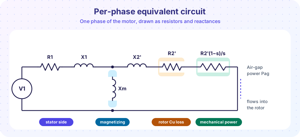
Quantities with a prime are referred to the stator. Many textbooks add a resistor in parallel with Xm for the core loss; to keep the arithmetic short we leave it out and add the core loss at the end.
Following the power
With V1 the phase voltage and I2' the referred rotor current:
Pin   = 3 V1 I1 cos φ                  electrical input
Pcu1  = 3 I1² R1                        stator copper loss
Pag   = Pin − Pcu1 − Pcore = 3 I2'² R2' / s
Pcu2  = s · Pag                         rotor copper loss
Pmech = (1 − s) · Pag                   mechanical power
Pout  = Pmech − Pfw                     shaft power (friction and windage removed)
T     = Pag / ωs = Pmech / ωm           torque, ωs = 2π ns/60, ωm = (1 − s) ωs
Two facts follow at once. First, rotor copper loss is a fixed fraction of the power crossing the gap, so a high slip wastes a high share of the power. Second, torque is proportional to air-gap power, so you can find it without knowing the shaft speed.
A worked example
A 400 V (line), 50 Hz, 4-pole, star-connected motor has R1 = 0.35 Ω, X1 = 0.9 Ω, R2' = 0.30 Ω, X2' = 0.9 Ω, Xm = 35 Ω. Find the currents, power and torque at s = 0.03.
The phase voltage is 400 / √3 = 231 V. The rotor branch is 0.30 / 0.03 + j0.9 = 10 + j0.9 Ω. Put Xm in parallel with it, add R1 + jX1, and divide the voltage by the result. Doing this by hand takes a page of complex arithmetic, so the program below does it. It gives a stator current of about 22.9 A at a power factor of 0.908 lagging, an input of 14.4 kW, an air-gap power of 13.8 kW, a rotor copper loss of 415 W (exactly 3 % of Pag) and a mechanical power of 13.4 kW. The torque is 13 832 W / 157.1 rad/s = 88.1 N·m. The efficiency of 93 % is optimistic because core, friction and stray losses are not yet subtracted.
Check any answer with the two identities Pcu2 = s · Pag and T = Pag / ωs. If they fail, a number is wrong.
Common misconceptions
"Slip is a loss." Slip is a speed ratio. The loss is s · Pag, which is small only when slip is small.
"The rotor frequency equals the supply frequency." Only at standstill. At rated load it is typically 1 to 3 Hz on a 50 Hz machine.
"The motor makes most torque at zero slip." At s = 0 the torque is zero. The torque rises with slip up to a maximum, as the next lesson shows.
Try it
First, a solver for the circuit. Change the parameters or the slip and watch the results move.
Press Run (or Ctrl + Enter) to see the result here.
Program input · what you'd type while the program runs
Type the answers before you press Run, one per line. Each time the program reads a line (with input()), it gets the next line from this box.
Second, see how current, power factor and efficiency change across the normal operating range.
Press Run (or Ctrl + Enter) to see the result here.
Program input · what you'd type while the program runs
Type the answers before you press Run, one per line. Each time the program reads a line (with input()), it gets the next line from this box.
Check your understanding
Quick check · 5 questions
of 5 answered You scored / 5 · perfect!
-
1. A 4-pole motor on 50 Hz runs at 1425 rpm. What is its slip?
ns = 1500 rpm, so s = (1500 − 1425) / 1500 = 0.05. -
2. What is the rotor current frequency at a slip of 0.04 on a 50 Hz supply?
f2 = s f = 0.04 × 50 = 2 Hz. -
3. Which part of the equivalent circuit represents the mechanical power?
The rotor resistance is split into R2' (the real copper) and R2'(1 − s)/s, whose power equals the mechanical power. -
4. The air-gap power is 20 kW and the slip is 0.04. What is the rotor copper loss?
Pcu2 = s × Pag = 0.04 × 20 kW = 0.8 kW. The mechanical power is the remaining 19.2 kW. -
5. Why is the current large when the rotor is locked (s = 1)?
At s = 1 the rotor resistance term is R2' only, so the impedance is low and the motor draws a current several times its rated value.
Summary
- Slip is
s = (ns − n) / ns; rotor frequency iss f. - The rotor resistance appears as
R2'/s = R2' + R2'(1 − s)/s; the second part is the mechanical power. Pcu2 = s · Pag,Pmech = (1 − s) · Pag,T = Pag / ωs.- Solving the per-phase circuit gives current, power factor, losses and torque at any slip.
Track your progress
Create a free account to tick off lessons and pick up where you left off on any device.
of Electrical Machines lessons completed