


















Lesson 29 of 45 · Synchronous Machines
The synchronous motor and the power angle
Understand how a synchronous motor carries load through the load angle, why it needs help to start, and how field current controls power factor through the V-curve.
Take an alternator, stop supplying mechanical power and connect its stator to the grid instead: it becomes a motor. The rotor still has DC-excited poles, the stator still makes a rotating field, and the rotor still turns at exactly synchronous speed. What changes is the direction of power flow and the sign of the load angle.
Synchronous motors are chosen for large, constant-speed drives such as compressors, crushers and mill drives, and because they offer something an induction motor cannot: you can adjust their power factor with the field current. They can even supply reactive power to the grid.
What you will learn
- How the load angle carries torque and why there is a maximum.
- How to calculate power, angle and pull-out limits.
- Why a synchronous motor does not start by itself and how damper windings fix that.
- How the V-curve links field current to armature current and power factor.
Key terms
Load angle δ: the angle between the rotor field axis and the stator's rotating field (equivalently, between E and V).
Pull-out torque: the maximum torque, reached at δ = 90°; beyond it the motor loses synchronism.
Damper winding: copper bars in the pole faces that let the motor start like an induction motor.
Over-excited: field current high enough that the motor draws leading current.
Synchronous condenser: a synchronous machine running without a mechanical load to supply or absorb reactive power.
Load angle and torque
With the stator resistance neglected, a motor on a supply V obeys V = E + jXs I, where E is the internal voltage set by the field. The rotor does not lag by slip; instead its poles sit a little behind the rotating field by an angle δ, like a car pulling a trailer with a stretchy tow rope. More load stretches the rope, so δ grows. The power is
P = 3 V E sin δ / Xs          (watts, three-phase, V and E in phase volts)
T = P / ωs
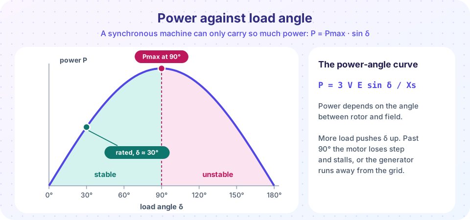
The maximum is Pmax = 3 V E / Xs at δ = 90°. Past that point more angle gives less torque, so the rotor falls out of step. Real machines run at 20° to 30° at rated load, leaving a margin of at least 2 for sudden load changes. Because the torque at a given angle goes with E, a stronger field raises the margin: over-exciting helps stability.
For example, with V = 6600 V (line, so 3810 V per phase), Xs = 15 Ω and a field that gives E = 1.2 V = 4573 V, the machine has Pmax = 3 × 3810 × 4573 / 15 = 3485 kW. It carries 1742 kW at 30°. A 1 MW load needs only δ = arcsin(1000 / 3485) = 16.7°.
Starting
At standstill the stator field sweeps past the rotor at 50 times a second. The rotor is pulled one way and then the other, so the average torque is zero. A synchronous motor therefore has no starting torque of its own. Three common cures:
- Damper (amortisseur) windings. Bars embedded in the pole faces and joined at the ends form a squirrel cage. The motor starts as an induction motor, with the field winding shorted through a discharge resistor so that it does not carry dangerous induced voltage. When it reaches about 95 % of synchronous speed the DC field is applied and the rotor pulls into step.
- A variable-frequency drive. Start at a low frequency and raise it slowly; the rotor stays locked to the field the whole time.
- A pony motor. A small motor brings the machine to speed, then the main supply is connected after synchronizing, as with a generator.
The damper bars also help in normal running: they damp the oscillations (hunting) of the rotor around its steady angle.
Power-factor control and V-curves
At a fixed mechanical load, the power P stays constant, so E sin δ stays constant. Changing the field current changes E, and the motor adjusts δ and the armature current. If you plot armature current against field current you get a V-shaped curve whose minimum is at unity power factor.
- Left of the minimum the motor is under-excited: it draws lagging current, like an induction motor.
- At the minimum the current is lowest and the power factor is one.
- Right of the minimum the motor is over-excited: it draws leading current and acts like a capacitor, supplying reactive power to the grid.
Heavier loads raise the whole curve. With no load, an over-excited machine is a synchronous condenser, used to hold the voltage at the end of a long transmission line. Large plants also use over-excited synchronous motors to correct the lagging power factor of nearby induction motors.
Common misconceptions
"A synchronous motor slows down when loaded." It keeps the same speed up to pull-out; only the load angle changes.
"More field current makes the motor run faster." Speed is fixed by frequency. Field current changes power factor and the pull-out margin.
"It can start on the supply like an induction motor." Without damper windings or a variable-frequency start it cannot start at all.
Try it
First, the power-angle relation for three excitation levels. Notice how the load angle for the same 1 MW load shrinks as E increases.
Press Run (or Ctrl + Enter) to see the result here.
Program input · what you'd type while the program runs
Type the answers before you press Run, one per line. Each time the program reads a line (with input()), it gets the next line from this box.
Second, the V-curves: armature current against field excitation (shown as E / V) for three constant loads. The dashed line connects the unity-power-factor points.
Press Run (or Ctrl + Enter) to see the result here.
Program input · what you'd type while the program runs
Type the answers before you press Run, one per line. Each time the program reads a line (with input()), it gets the next line from this box.
Check your understanding
Quick check · 5 questions
of 5 answered You scored / 5 · perfect!
-
1. At what load angle does a synchronous motor reach its maximum power (neglecting resistance)?
P = Pmax sin δ is largest at δ = 90°; beyond it the motor loses synchronism. -
2. A synchronous motor is over-excited. It then draws
Over-excitation makes E larger than V, so the motor draws leading current and can supply reactive power. -
3. Why does a synchronous motor have no starting torque on a fixed-frequency supply?
At standstill the rotating field passes the rotor poles too fast for them to lock on, so the torque alternates and averages to zero. -
4. With V = 3810 V and E = 4573 V per phase and Xs = 15 Ω, the maximum three-phase power is closest to
Pmax = 3 V E / Xs = 3 × 3810 × 4573 / 15 ≈ 3.49 MW. -
5. What is the main purpose of damper windings in a synchronous motor?
The damper cage provides starting torque and damps oscillations of the rotor around its steady angle.
Summary
- A synchronous motor runs at exactly
120 f / P; load changes the angleδ, not the speed. P = 3 V E sin δ / Xs; maximum at 90°, with rated operation at about 20° to 30°.- It cannot start alone: use damper windings, a variable-frequency drive or a pony motor.
- Field current controls power factor: the V-curve has its minimum current at unity power factor; over-excited operation is leading.
Next: Chapter review
Track your progress
Create a free account to tick off lessons and pick up where you left off on any device.
of Electrical Machines lessons completed