


















Lesson 9 of 46 · Diodes and Rectifiers
Zener regulators, clippers and protection diodes
Design a Zener shunt regulator, build diode clippers, and protect circuits from voltage spikes, with worked numbers and simulations you can run.
Forward conduction is only half of a diode's behavior. Push a diode into reverse breakdown and the voltage across it stays nearly constant while the current changes a lot. That property, designed on purpose, gives the Zener diode, a cheap voltage reference and regulator. Add a few more diode tricks (limiting a signal's height, steering away the spike from a relay coil) and you have a toolkit of small circuits that appear in nearly every product.
This lesson designs a Zener regulator step by step, then turns to clippers, clampers and protection.
What you will learn
- How Zener breakdown works and what the Zener voltage and dynamic resistance mean
- How to choose the series resistor and Zener power rating for a regulator
- How to estimate line and load regulation
- How clippers, clampers and flyback diodes shape or protect signals
Key terms
Zener voltage (V_z): the reverse breakdown voltage at which a Zener diode regulates, specified at a test current.
Shunt regulator: a regulator that sits in parallel with the load and soaks up the surplus current.
Line regulation: how much the output changes when the input voltage changes.
Load regulation: how much the output changes when the load current changes.
Clipper: a circuit that limits a waveform above or below a certain level.
Flyback diode: a diode across an inductive load that gives the coil current a path when the switch opens.
The Zener diode
A normal diode is damaged by sufficient reverse voltage. A Zener is built with a controlled breakdown region and enough power rating to sit there. Two physical mechanisms cause the breakdown: the Zener effect (quantum tunneling, dominant below about 5 V) and avalanche multiplication (dominant above about 7 V). Around 5 to 6 V they partly cancel, so a Zener near 5.6 V has the lowest temperature drift. Whatever the cause, such diodes are all called Zener diodes. They come in a range of voltages from about 2.4 V up to 200 V in standard values: 3.3 V, 5.1 V, 9.1 V, 12 V and so on.
In the circuit symbol the diode points the usual way but the cathode bar has bent ends. You connect it reversed: cathode to the more positive side. In breakdown, the voltage is V_z plus a small term proportional to the current: V = V_z + r_z·ΔI, where r_z is the dynamic resistance, typically some tens of ohms for a small-signal part. The smaller r_z, the better the regulation.
Designing a shunt regulator
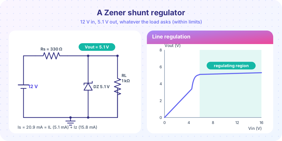
The circuit in the figure: an unregulated input V_in, a series resistor R_s, a Zener to ground, and the load in parallel with the Zener.
KCL at the output node: the current through R_s splits between the Zener and the load.
Is = (Vin − Vz) / Rs
Iz = Is − IL
Example. V_in = 12 V, V_z = 5.1 V, R_s = 330 Ω, R_L = 1 kΩ.
- I_s = (12 − 5.1)/330 = 20.9 mA
- I_L = 5.1/1000 = 5.1 mA
- I_z = 20.9 − 5.1 = 15.8 mA
- Zener power = 5.1 V × 15.8 mA = 80.6 mW
- Resistor power = (6.9 V)² / 330 = 144 mW, so a ½ W resistor is comfortable
If the load is removed, the Zener takes everything: I_z = 20.9 mA and power 107 mW. A common 500 mW part handles that easily.
Choosing R_s in general
Two conditions bound R_s. At the lowest input voltage and highest load current the Zener must still carry its minimum useful current I_z,min (a milliamp or two, so it stays in breakdown):
Rs ≤ (Vin,min − Vz) / (IL,max + Iz,min)
At the highest input voltage and no load, the Zener current and power must stay below the maximum ratings:
Iz,max = (Vin,max − Vz) / Rs Pz = Vz × Iz,max ≤ rating
Suppose V_in varies from 10.5 V to 13.5 V and the load draws 0 to 10 mA, with I_z,min = 2 mA. Then R_s ≤ (10.5 − 5.1)/(12 mA) = 450 Ω. Choose the standard 390 Ω. Check: at 10.5 V and 10 mA the Zener carries 13.8 − 10 = 3.8 mA (OK). At 13.5 V and no load it carries 21.5 mA, dissipating 110 mW (OK for a 500 mW part).
How good is the regulation?
Treat the Zener as V_z in series with r_z. Then the output changes with the input by
ΔVout / ΔVin ≈ rz / (Rs + rz)
With r_z = 20 Ω (a plausible figure for a small Zener) and R_s = 390 Ω, a 1 V change at the input changes the output by only about 49 mV, roughly twenty times better than a plain divider. For load changes the output moves by about r_z × ΔI_L: a 10 mA swing in load current changes the output by around 0.2 V. A shunt regulator is simple but wasteful (it burns power even with no load) and is used only for small currents or as a reference feeding a transistor that does the heavy lifting (chapter 8).
Clippers
A clipper (or limiter) removes the part of a signal above or below a threshold. The simplest version is a series resistor with a diode to ground. In the positive half-cycle the diode conducts once the input exceeds 0.7 V, holding the output near 0.7 V. The negative half passes through unchanged (output at the input value). Adding a second diode in the opposite direction clips the negative half at −0.7 V as well. Two back-to-back diodes to ground limit the output to about ±0.7 V no matter how large the input; this is the heart of a classic guitar distortion pedal, and is a standard way to protect an amplifier or analog input from overdrive.
Variations:
- A biased clipper puts a DC source in series with the diode to change the clipping level (for example, clip at 3.7 V).
- A Zener clipper uses a Zener in series with a diode (opposite directions) to clip at V_z + 0.7 V.
- Input protection clips to the supply rails: one diode from the input to V_cc and one to ground, behind a series resistor. A voltage far above the rail turns on the upper diode and the series resistor limits the current.
Clampers
A clamper shifts a waveform up or down without changing its shape. A capacitor in series with the signal and a diode to ground form the basic circuit. During the first cycle the diode charges the capacitor to the signal's peak, and thereafter the capacitor acts as a battery adding a fixed offset. The waveform sits entirely above (or below) zero, with its extreme at about the diode drop. Clampers restore DC levels in video circuits and are the first half of a voltage-doubler.
Flyback diodes
Current in an inductor cannot change instantly: V = L·di/dt. When a transistor suddenly switches off a relay coil, the coil tries to keep the current flowing, and the voltage across it spikes (hundreds of volts if nothing absorbs it), destroying the transistor. A flyback diode (also called freewheeling or snubber diode) connected in reverse across the coil gives that current a harmless loop: it conducts the spike (with only a 0.7 V drop) and the coil's energy decays through its own resistance. Every transistor-driven relay, solenoid and motor needs one.
Common misconceptions
"A Zener regulates at any current." It regulates only while its current exceeds a minimum, and below its power rating. Check the worst cases at both input limits.
"A Zener should be connected forward like other diodes." Forward, it behaves like an ordinary 0.7 V diode. It regulates only in reverse breakdown.
"The series resistor is optional." Without it, the Zener would carry unlimited current and burn out. The resistor sets the current.
Try it
First, a regulator design explorer. It computes the Zener current and power for your values, then plots how the output voltage varies with load current. Note the cliff at the right: once the load takes all of the available current, the Zener turns off and regulation is lost.
Press Run (or Ctrl + Enter) to see the result here.
Program input · what you'd type while the program runs
Type the answers before you press Run, one per line. Each time the program reads a line (with input()), it gets the next line from this box.
Second, a clipper. A 5 V peak sine passes through a 1 kΩ series resistor into two back-to-back diodes. The plot shows the input and the clipped output, and the output spectrum gets richer in harmonics, which is why clipping sounds like distortion on a guitar.
Press Run (or Ctrl + Enter) to see the result here.
Program input · what you'd type while the program runs
Type the answers before you press Run, one per line. Each time the program reads a line (with input()), it gets the next line from this box.
Check your understanding
Quick check · 5 questions
of 5 answered You scored / 5 · perfect!
-
1. In which direction is a Zener diode connected to regulate?
A Zener regulates in reverse breakdown, with the cathode toward the more positive supply. -
2. A 12 V source feeds a 5.1 V Zener through 470 Ω. With no load, what is the Zener current?
I = (12 − 5.1)/470 = 14.7 mA. -
3. The Zener in the previous question dissipates about how much power?
P = V_z × I_z = 5.1 V × 14.7 mA = 75 mW. -
4. Two diodes connected back to back to ground after a series resistor limit a signal to about what range?
Each diode conducts for one polarity once the voltage exceeds about 0.7 V. -
5. What is a flyback diode for?
The coil's current cannot stop instantly; the diode conducts it so the voltage spike stays near 0.7 V.
Summary
- A Zener diode regulates in reverse breakdown; connect it with the cathode to the positive side through a series resistor.
- Design R_s so the Zener keeps a minimum current at the worst input and load, and stays below its power rating at the other extreme.
- Line regulation ≈ r_z/(R_s + r_z); a shunt regulator wastes power but is simple.
- Clippers limit a signal's height, clampers shift its DC level, and flyback diodes protect against inductive spikes.
Next: Chapter 2 review
Track your progress
Create a free account to tick off lessons and pick up where you left off on any device.
of Analog Electronics lessons completed