


















Lesson 45 of 46 · Projects and Practice
Analog electronics cheat sheet
One-page recap of the key formulas for BJT amplifiers, op-amps, filters, oscillators and power supplies, with constants, rules of thumb and a formula calculator.
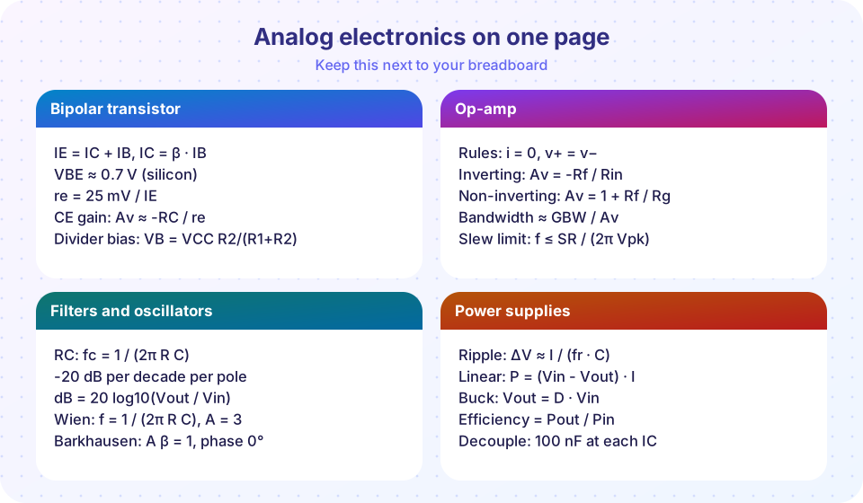
This page is the one you print and stick above your workbench. It gathers the formulas and rules of thumb from chapters 5 to 8 into a single place, with the constants you need and a few habits that save hours of debugging. It is a memory aid, not a replacement for understanding: if a formula looks unfamiliar, follow its link to the lesson that derives it.
What you will learn
- Find any key formula of the track quickly.
- Remember the constants and typical values.
- Apply the rules of thumb for fast estimates.
Amplifiers and bias
| Quantity | Formula | Notes |
|---|---|---|
| Decibels | dB = 20 log10(Vout / Vin); 10 log10(P2 / P1) |
x2 = 6 dB, x10 = 20 dB |
| Loaded gain | Av0 · Rin/(Rs + Rin) · RL/(RL + Rout) |
Want high Rin, low Rout |
| Load line | VCE = VCC - IC (RC + RE) |
Q-point near VCC / 2 |
| Divider bias | VB = VCC R2/(R1 + R2), VE = VB - 0.7, IE = VE / RE |
Divider current ≈ 10 × IB |
Small-signal re |
re = VT / IE ≈ 25 mV / IE |
Same as 1 / gm |
| CE gain | bypassed -RC / re; unbypassed -RC / (re + RE) |
Parallel RL with RC |
| CE input resistance | R1 ∥ R2 ∥ β (re + RE_unbypassed) |
|
| Distortion | second harmonic ≈ vin / (4 VT) (bypassed stage) |
Keep vin of a few mV |
Op-amps
| Quantity | Formula | Notes |
|---|---|---|
| Golden rules | i+ = i- = 0; v+ = v- with negative feedback |
|
| Inverting | Av = -Rf / Rin; input resistance Rin |
|
| Non-inverting | Av = 1 + Rf / Rg |
High input resistance |
| Summer | vout = -Rf Σ(vk / Rk) |
|
| Difference | (R2 / R1)(v2 - v1) with R4/R3 = R2/R1 |
Matching sets CMRR |
| Integrator / differentiator | -(1/RC) ∫ vin dt / -RC dvin/dt |
|
| Bandwidth | GBW / gain |
|
| Slew limit | 2π f Vp ≤ SR; f_max = SR / (2π Vp) |
|
| Offset error | Vos (1 + Rf / Rin) |
Bias current: match input resistances |
Filters and oscillators
| Quantity | Formula | Notes |
|---|---|---|
| RC cutoff | fc = 1 / (2π R C) |
-3 dB, ∓45° at fc |
| Roll-off | -20 dB/decade per pole | 2nd order: -40 dB/decade |
| Time constant, rise time | τ = R C; t10-90 = 0.35 / fc = 2.2 τ |
|
| Sallen-Key (unity gain) | f0 = 1/(2π√(R1R2C1C2)), Q = √(R1R2C1C2)/(C2(R1+R2)) |
Equal R: Q = ½ √(C1/C2) |
| Butterworth | Q = 0.707 (2nd order); Bessel 0.577 |
4th order: 0.541 and 1.307 |
| Barkhausen | A·β = 1 in magnitude, phase 0° |
|
| Wien bridge | f = 1 / (2π R C), amplifier gain 3 |
|
| Phase-shift | f = 1 / (2π R C √6), gain ≥ 29 |
|
| Relaxation (op-amp) | T = 2 R C ln((1 + β)/(1 - β)) |
β = R2/(R1 + R2) |
Power supplies
| Quantity | Formula | Notes |
|---|---|---|
| Peak (bridge) | Vrms √2 - 1.4 V |
Include mains tolerance |
| Ripple | ΔV ≈ I / (fr C) |
fr = 2f for full-wave |
| Zener resistor | Rs = (Vin(min) - Vz) / (Iz(min) + IL(max)) |
Check worst-case power |
| Linear dissipation | P = (Vin - Vout) I; η ≤ Vout / Vin |
|
| Junction temperature | Tj = Ta + P θJA |
Limit about 125 °C |
| Buck | Vout = D Vin; ΔIL = (Vin - Vout) D / (L fsw) |
Ripple 20-40% of load |
| Buck output ripple | ΔVout ≈ ΔIL / (8 fsw C) + ΔIL · ESR |
|
| Boost | Vout = Vin / (1 - D) |
Constants and typical values
| Item | Value |
|---|---|
Boltzmann constant k |
1.380649 × 10⁻²³ J/K |
Elementary charge q |
1.602177 × 10⁻¹⁹ C |
Thermal voltage VT = kT/q |
about 25.9 mV at 300 K (25 mV is common) |
| Silicon diode / BE drop | 0.6 - 0.7 V (falls about 2 mV per °C) |
| Bridge rectifier drop | about 1.4 V |
| 7805 dropout | about 2 V; LDO 0.1 - 0.5 V |
| Mains peak | 325 V (230 V rms), 170 V (120 V rms) |
| E12 series | 1.0 1.2 1.5 1.8 2.2 2.7 3.3 3.9 4.7 5.6 6.8 8.2 |
Rules of thumb
- Always do the DC analysis first; check the Q-point before the gain.
- A 1 mA emitter current means
re ≈ 25 Ω; a 10 mA current means about 2.5 Ω. - A pole at
fccosts 45° of phase atfcand 90° far above. - Choose op-amp circuit resistors between 1 kΩ and 100 kΩ.
- Gain times bandwidth equals GBW; always check the slew rate for big, fast signals.
- Give a linear regulator 2-3 V more than dropout at the ripple minimum, but no more: heat grows with the drop.
- Place a 100 nF capacitor at every IC supply pin, as close as possible.
- If it oscillates when it should not: add decoupling, shorten loops, add a small series resistor before a capacitive load.
Try it
The first example is a formula pack: a small library of the key calculations with example calls, so you can reuse it in your own scripts. All functions apply the formulas on this page.
Press Run (or Ctrl + Enter) to see the result here.
Program input · what you'd type while the program runs
Type the answers before you press Run, one per line. Each time the program reads a line (with input()), it gets the next line from this box.
The second example is a standard-value finder. Enter a resistance (or capacitance) and see the nearest E12 and E24 preferred values and the error from the exact value.
Check your understanding
Quick check · 4 questions
of 4 answered You scored / 4 · perfect!
-
1. Which formula gives the voltage gain of a bypassed common-emitter stage?
With the emitter bypassed, Av = -RC / re. -
2. What is the peak voltage of a 120 V rms mains supply?
120 × 1.414 = 170 V. -
3. Which rule of thumb gives re for a 5 mA emitter current?
re = 25 mV / 5 mA = 5 Ω. -
4. Which expression gives the highest frequency of a full-amplitude, undistorted sine wave from an op-amp?
That is the full-power bandwidth set by the slew rate.
Summary
- Keep the formulas grouped by topic; know where each comes from.
- Remember the constants (
VT ≈ 25 mV,VBE ≈ 0.7 V, bridge drop 1.4 V). - Use the rules of thumb for fast estimates, then verify with a calculation or simulation.
Next: Where to go next
Track your progress
Create a free account to tick off lessons and pick up where you left off on any device.
of Analog Electronics lessons completed