


















Lesson 46 of 46 · Projects and Practice
Where to go next: further study in analog electronics
Plan your next steps after analog electronics: deeper circuit theory, signals and systems, control, DSP, embedded systems and Arduino projects, plus topics worth exploring.
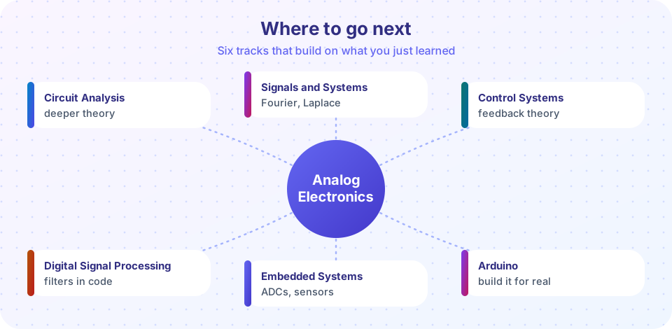
You now have a working vocabulary and a toolbox: you can bias a transistor, design an op-amp stage, shape frequencies with filters, build an oscillator, and power it all cleanly. That is a solid foundation, but analog electronics is a deep field, and the right next step depends on what you want to do. This lesson maps the neighbouring subjects, shows how each one builds on what you learned, and suggests a few practical projects.
What you will learn
- See how analog electronics connects to neighbouring subjects.
- Choose a next track that fits your goal.
- Pick practical projects to consolidate your skills.
Six directions
Deeper theory: circuit analysis
If the algebra in this track felt like a series of tricks, the Circuit Analysis track gives you the systematic methods behind them: nodal and mesh analysis, Thevenin and Norton equivalents, AC steady state with phasors, resonance and transients. These methods let you solve any linear circuit, not just the textbook ones, and they are what simulators (SPICE) do for you automatically.
The mathematics of signals: signals and systems
Every filter in chapter 7 is a linear time-invariant system. Signals and Systems develops the tools that describe them: convolution, the Fourier transform (why "frequency response" works), and the Laplace transform (why poles and Q behave the way they do). If the transfer functions 1/(1 + sRC) made you curious, this is where they come from.
Feedback beyond the op-amp: control systems
Negative feedback stabilised your op-amp gain. Control Systems generalises the idea to motors, heaters and drones: stability, gain and phase margin, PID controllers, root locus. The loop-gain and Barkhausen ideas from the oscillator lesson reappear as the stability criterion: the same condition that makes an oscillator oscillate makes a badly designed control loop go unstable.
From analog to digital: digital signal processing
Your anti-aliasing filter was the doorway between worlds. Digital Signal Processing teaches what happens after the ADC: sampling theory, digital filters (FIR and IIR), the FFT. Many analog filters have digital equivalents; the demo below shows an RC filter and its digital twin.
Building systems: embedded systems and Arduino
An ADC, a microcontroller and a few analog stages make a measurement system. Embedded Systems shows how to organise the software and hardware of such a device; Arduino is a friendly way to start building immediately with sensors, op-amp front ends and power regulators like the ones you designed.
Topics inside analog electronics worth exploring
Within the field itself, here are topics this track only touched:
- Frequency response of transistor amplifiers at high frequencies: Miller effect, cascode stages, bandwidth of a CE amplifier.
- Differential pairs and operational amplifier internals: how the chip you used is built, and why its GBW and slew rate are what they are.
- Power amplifiers: class A, B and AB output stages, efficiency and heat.
- Noise analysis: thermal, shot and flicker noise; designing for low-noise measurements.
- Data converters: how ADCs and DACs work (SAR, delta-sigma), and their errors.
- Phase-locked loops, mixers and RF circuits for communication systems.
- PCB design and EMC: layout, grounding, shielding and compliance.
- Simulation: SPICE (LTspice, ngspice) lets you test any circuit before you build it.
Practical projects
- Bench power supply: a transformer, bridge, filter capacitor and an adjustable linear regulator (LM317) with current limiting.
- Guitar or microphone preamplifier with a tone control built from the filters of chapter 7.
- Function generator: a Wien-bridge or relaxation oscillator with a buffer and adjustable amplitude.
- Light or temperature sensor board feeding the ADC of a microcontroller through an op-amp stage, following the sensor chain project.
- Buck converter from an off-the-shelf controller chip: measure ripple and efficiency and compare with your calculations.
For each project, first predict the results with the formulas, then simulate, then build and measure. The loop of predict-simulate-measure is the real skill.
Try it
The first example is a "choose your path" helper. Pick your goal and it suggests a next track.
The second example connects this track to digital signal processing. It converts the analog RC low-pass of lesson 7 (fc = 1 kHz) into a digital IIR filter running at 8 kHz using the bilinear transform, and compares the two frequency responses. The two agree closely at low frequencies and drift apart near the Nyquist frequency (an effect called frequency warping), which is why digital design needs care.
Press Run (or Ctrl + Enter) to see the result here.
Program input · what you'd type while the program runs
Type the answers before you press Run, one per line. Each time the program reads a line (with input()), it gets the next line from this box.
The third example links to control systems. A voltage follower built from an op-amp with GBW = 1 MHz behaves like a first-order system. The simulation shows its step response and checks the rise time against 0.35 / bandwidth.
Press Run (or Ctrl + Enter) to see the result here.
Program input · what you'd type while the program runs
Type the answers before you press Run, one per line. Each time the program reads a line (with input()), it gets the next line from this box.
Check your understanding
Quick check · 3 questions
of 3 answered You scored / 3 · perfect!
-
1. Which track gives you the mathematics (Fourier and Laplace transforms) behind frequency response?
Signals and Systems develops convolution, Fourier and Laplace transforms. -
2. Which topic generalises negative feedback to motors, heaters and robots?
Control theory deals with stability and performance of feedback loops. -
3. What is a good way to learn from a circuit project?
Comparing prediction, simulation and measurement is how you find what you misunderstood.
Summary
- Circuit Analysis deepens the theory; Signals and Systems explains the mathematics of filters; Control Systems generalises feedback.
- Digital Signal Processing continues where the ADC ends; Embedded Systems and Arduino turn circuits into gadgets.
- Within analog electronics, high-frequency amplifiers, noise, power amplifiers, data converters and PCB design are the next topics.
- The predict, simulate, measure loop is the habit that makes you a designer.
Track your progress
Create a free account to tick off lessons and pick up where you left off on any device.
of Analog Electronics lessons completed