


















Lesson 40 of 46 · Power Supplies and Practical Design
Chapter 8 review: power supplies and practical design
Review rectifiers, ripple, linear and switching regulators and practical decoupling with a recap table, a full supply design calculator and a ten-question quiz.
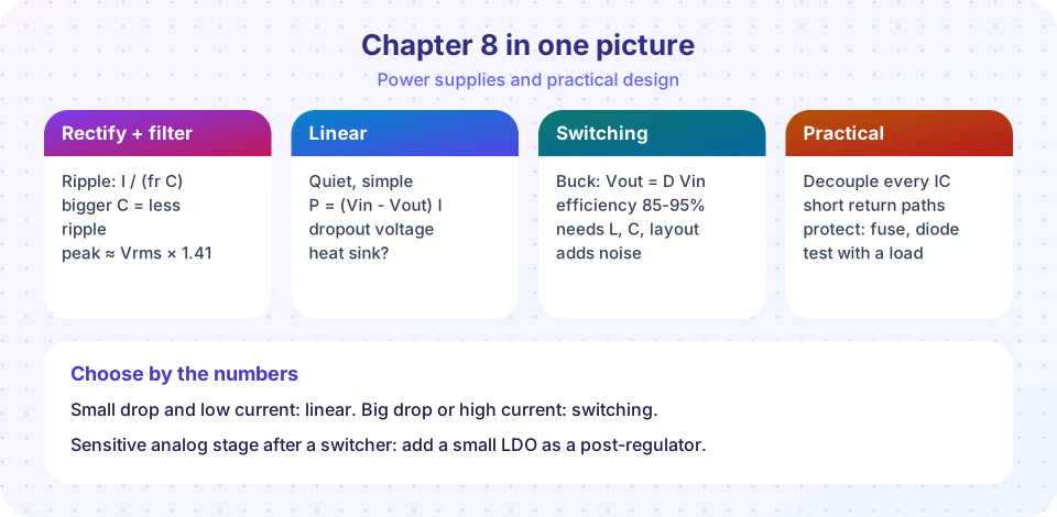
You followed a voltage from the wall to a clean rail in four steps: the transformer lowered it, the rectifier made it unipolar, the capacitor smoothed it, and the regulator fixed it. You also learned the habits that keep real boards quiet. This review puts the key numbers in one place and walks through a complete design.
Recap table
| Topic | Key result | Lesson |
|---|---|---|
| Bridge output peak | Vrms · √2 - 1.4 V |
Rectifiers and ripple |
| Ripple | ΔV ≈ I / (fr · C), fr = 2f for full-wave |
same |
| Regulator input minimum | Vpeak - ΔV at low mains must exceed Vout + dropout |
same |
| Zener resistor | Rs = (Vin(min) - Vz) / (Iz(min) + IL(max)) |
Linear regulators |
| Linear dissipation | (Vin - Vout) · I; efficiency at most Vout / Vin |
same |
| Junction temperature | Tj = Ta + P · θJA |
same |
| Buck | Vout = D · Vin; ΔIL = (Vin - Vout) D / (L fsw) |
Switching and practical |
| Ideal output ripple | ΔVout ≈ ΔIL / (8 fsw C) plus ΔIL · ESR |
same |
| Decoupling | 100 nF ceramic next to each IC pin pair, bulk capacitor nearby | same |
A complete design in six steps
Suppose you need 5 V at 0.5 A for a small analog circuit, from a 50 Hz mains transformer and a linear regulator.
- Regulator. A 7805 needs at least 7 V in. Choose the capacitor so that the lowest ripple voltage stays above that even with mains 10% low.
- Transformer. Try 9 V rms. At -10% mains,
Vrms = 8.1 V, so the peak is8.1 × 1.414 - 1.4 = 10.05 V. - Capacitor. For
ΔV = 1.5 Vallowed:C = I / (fr · ΔV) = 0.5 / (100 × 1.5) = 3,300 µF; pick 4,700 µF. The ripple is then1.06 Vand the minimum input is10.05 - 1.06 = 9.0 V, above 7 V: OK. - Dissipation. At nominal mains (+10% worst case) the average input is about 12 V, so
P = (12 - 5) × 0.5 = 3.5 W, which needs a heat sink withθSAof about 18 °C/W or better (see the previous lesson). - If the heat is too much, use a switching converter, or lower the transformer to 7.5 V rms and accept less headroom.
- Details. Add the input and output capacitors at the regulator, a fuse on the primary, a 100 nF capacitor at each analog chip and a ground layout that keeps the capacitor's charging pulses away from the sensitive section.
The calculator below runs this recipe for any values you choose.
Try it
The first example is a design calculator that follows the six steps for a linear supply and checks whether the result is feasible. It uses the standard approximations from this chapter.
Press Run (or Ctrl + Enter) to see the result here.
Program input · what you'd type while the program runs
Type the answers before you press Run, one per line. Each time the program reads a line (with input()), it gets the next line from this box.
The second example is a short practice game: for each supply requirement, choose the better regulator type. It is for self-testing, not a replacement for reading datasheets.
Check your understanding
Quick check · 10 questions
of 10 answered You scored / 10 · perfect!
-
1. A bridge rectifier with a 12 V rms secondary on 50 Hz mains feeds 1 A through 4,700 µF. What is the approximate ripple?
ΔV = 1 / (100 × 0.0047) = 2.13 V. -
2. The peak DC voltage from that 12 V rms bridge secondary (before ripple) is about:
12 × 1.414 = 16.97 V, minus 1.4 V for the two diodes = 15.6 V. -
3. A 7809 runs from a 15 V input at 0.3 A. What power does it dissipate?
(15 - 9) × 0.3 = 1.8 W. -
4. Which regulator is best for turning 5 V into 12 V?
Linear regulators and Zener regulators can only lower a voltage; boosting needs a switching converter. -
5. What is the main downside of a switching regulator for a sensitive analog circuit?
The fast edges produce noise that must be filtered or post-regulated. -
6. What does a 100 nF decoupling capacitor at an IC do?
It provides a nearby local reservoir, so the long supply trace does not have to deliver the spikes. -
7. What limits the maximum efficiency of a linear regulator?
It passes the load current from Vin to Vout, burning the difference as heat. -
8. An LDO has a dropout of 0.3 V. What is the minimum input needed for a 3.3 V output?
Vin(min) = Vout + dropout = 3.3 + 0.3 = 3.6 V. -
9. Buck converter: Vin = 15 V, Vout = 3 V. What is the ideal duty cycle?
D = Vout / Vin = 3 / 15 = 0.2. -
10. Why use a short ground spring on an oscilloscope probe when checking supply ripple?
A long lead is an antenna with inductance; a short spring measures the real ripple.
Summary
- Design backward from the regulator: ripple minimum at low mains must exceed
Vout + dropout. - Linear: simple, quiet,
P = (Vin - Vout) I; switching: efficient, noisier. - Buck
D = Vout / Vin; boost and buck-boost handle step-up and inversion. - Decouple, keep loops small, protect inputs, and measure carefully.
Track your progress
Create a free account to tick off lessons and pick up where you left off on any device.
of Analog Electronics lessons completed