


















Lesson 28 of 46 · Operational Amplifiers
Op-amp circuits: summer, difference, integrator and differentiator
Use the golden rules to design the summing amplifier, difference amplifier, integrator and differentiator, with worked numbers, CMRR from resistor tolerance and runnable demos.
Once you can solve the inverting and non-inverting amplifiers, a whole family of useful circuits follows by changing what is connected around the op-amp. Add more inputs through resistors and you get a mixer. Feed signals to both inputs and you get a subtractor. Replace a resistor by a capacitor and the circuit starts doing calculus on the signal. In this lesson you will derive four of these building blocks using nothing but the two golden rules.
What you will learn
- Derive the output of the summing and difference amplifiers.
- Explain why resistor matching decides the quality of a difference amplifier.
- Compute integrator and differentiator outputs for simple inputs.
- Recognise practical problems: drift, noise and saturation.
Key terms
Summing amplifier: an inverting amplifier with several input resistors that combines signals into one weighted sum.
Common-mode signal: the part of the two inputs that is identical, for example hum picked up on both wires.
CMRR: common-mode rejection ratio, how well a difference amplifier ignores the common-mode part, in dB.
Integrator: a circuit whose output is proportional to the running integral of the input.
Differentiator: a circuit whose output is proportional to the rate of change of the input.
The summing amplifier
Take the inverting amplifier and connect several inputs, each through its own resistor, to the virtual earth. Each resistor carries vk / Rk, and these currents add because the node does not move:
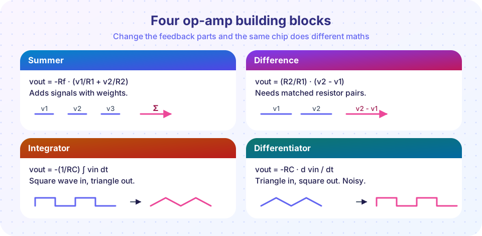
vout = -Rf · (v1/R1 + v2/R2 + v3/R3 + ...)
If all input resistors are equal to R, then vout = -(Rf / R)(v1 + v2 + v3): a true sum. Different resistors give different weights. Because every input sees a virtual earth, the sources do not interact: changing v1 does not disturb v2. This is why the summer is the heart of audio mixers and of simple digital-to-analog converters.
Worked example. v1 = 1 V through R1 = 10 kΩ, v2 = 0.5 V through R2 = 20 kΩ, Rf = 10 kΩ. Then vout = -10k · (1/10k + 0.5/20k) = -(1 + 0.25) = -1.25 V.
The difference amplifier
Put v1 through R1 to the − input with feedback R2, and v2 through R3 to the + input with R4 to ground. Superposition and the golden rules give
vout = v2 · [R4 / (R3 + R4)] · (1 + R2 / R1) - v1 · (R2 / R1)
If R3 = R1 and R4 = R2, the first term simplifies and
vout = (R2 / R1) · (v2 - v1)
Only the difference is amplified. That is the whole point: if both wires pick up the same hum, the hum cancels. But cancellation is only perfect if the resistor ratios match exactly. A mismatch turns a common-mode signal into a small differential signal that is amplified along with the real one. With 1% resistors and a gain of 10, the worst-case CMRR is only about 49 dB (about 69 dB with 0.1% parts), which is why instrumentation amplifiers use laser-trimmed matched networks. The third demo below computes it.
Input resistance is only R1 (and R3 + R4) from each side, so the circuit loads its source. Sensors with high source resistance need buffers in front.
The integrator
Swap the feedback resistor for a capacitor C. The input current vin / R flows into the capacitor, which builds up charge. The output is the voltage across the capacitor (negated because of the virtual earth):
vout(t) = -(1 / (R·C)) · ∫ vin dt + vout(0)
For a constant input V, vout is a ramp with slope -V / (RC). With R = 10 kΩ, C = 100 nF, RC = 1 ms. A square wave of ±1 V with 1 ms half-periods therefore makes the output ramp by 1 V / 1 ms × 1 ms = 1 V each half-period: a triangle wave 1 V peak to peak.
Practical problem: a real op-amp has a small DC offset. The integrator sees it as a constant input and ramps until it hits a supply rail. The usual cure is a large resistor Rf in parallel with C, which limits the DC gain to Rf / R and turns the circuit into a low-pass filter for very low frequencies.
The differentiator
Swap the input resistor for a capacitor instead:
vout(t) = -R·C · d(vin)/dt
A triangle wave in produces a square wave out, because the slope of a triangle is constant on each side. But a differentiator has gain that rises with frequency (|Av| = 2π f R C), so it amplifies noise terribly and tends to oscillate with the op-amp's own phase lag. Practical differentiators add a small series resistor with the capacitor, which flattens the gain above 1 / (2π R_s C).
A word on comparators
If you remove the feedback entirely, the huge open-loop gain pushes the output to one rail or the other depending on which input is higher. That is a comparator. Dedicated comparator chips are faster and have defined output levels, so avoid using a general op-amp as a comparator in precision work.
Common misconceptions
"The summing amplifier output is positive." It is inverted. To get a positive sum, follow it with another inverting stage of gain -1.
"Any four resistors will do in a difference amplifier." Only matched ratios R2/R1 = R4/R3 reject common-mode signals well.
"An ideal integrator holds a steady DC value." With any input offset, the output drifts to a rail. Real integrators need a reset switch or a DC-limiting resistor.
Try it
The first example simulates the integrator and the differentiator on sampled waveforms, so you can see the square-to-triangle and triangle-to-square behaviour. It is a numerical model of the ideal circuits, not a simulation of a real chip.
Press Run (or Ctrl + Enter) to see the result here.
Program input · what you'd type while the program runs
Type the answers before you press Run, one per line. Each time the program reads a line (with input()), it gets the next line from this box.
The second example is a three-channel mixer built on the summing amplifier. Set each input voltage and its resistor; the output is -Rf × Σ(vk / Rk) limited to the ±13 V range of the supply.
The third example measures how resistor tolerance destroys the common-mode rejection of a difference amplifier by trying every worst-case combination.
Press Run (or Ctrl + Enter) to see the result here.
Program input · what you'd type while the program runs
Type the answers before you press Run, one per line. Each time the program reads a line (with input()), it gets the next line from this box.
Check your understanding
Quick check · 5 questions
of 5 answered You scored / 5 · perfect!
-
1. A summing amplifier has Rf = 10 kΩ and three 10 kΩ input resistors with inputs 1 V, 2 V and 0.5 V. What is the output?
vout = -(10k/10k)(1 + 2 + 0.5) = -3.5 V; the summer inverts. -
2. A difference amplifier has R1 = R3 = 5 kΩ and R2 = R4 = 50 kΩ. With v1 = 2.00 V and v2 = 2.05 V, what is vout?
Gain is R2/R1 = 10 and the difference is 0.05 V, so vout = 0.5 V. -
3. An integrator has R = 100 kΩ, C = 10 nF and a constant +0.5 V input. How fast does the output ramp?
RC = 1 ms; slope = -V / RC = -0.5 / 0.001 = -500 V/s. -
4. Why is a plain differentiator rarely used as shown?
|Av| = 2π f R C grows with f. Practical versions add a series resistor to limit high-frequency gain. -
5. What limits the CMRR of a difference amplifier built from discrete resistors?
A mismatch between R2/R1 and R4/R3 converts common-mode input into a differential output.
Summary
- Summer:
vout = -Rf Σ(vk / Rk); inputs do not interact because of the virtual earth. - Difference amplifier:
vout = (R2 / R1)(v2 - v1)when ratios match; matching sets CMRR. - Integrator:
vout = -(1/RC)∫vin dt; differentiator:vout = -RC · dvin/dt. - Real circuits add drift control (integrator) and gain limiting (differentiator).
Next: Real op-amp limits
Track your progress
Create a free account to tick off lessons and pick up where you left off on any device.
of Analog Electronics lessons completed