


















Lesson 32 of 46 · Filters and Oscillators
RC filters: low-pass, high-pass and the -3 dB point
Derive the first-order RC low-pass and high-pass filters, compute the cutoff frequency, gain and phase, read a Bode plot and avoid loading mistakes.
The humble RC network, one resistor and one capacitor, is the simplest filter, and almost everything else in this chapter grows from it. It is also all around you: the circuit that smooths a button press, the tone knob on a guitar, the input of every audio amplifier. Understanding it thoroughly gives you the vocabulary (cutoff, roll-off, phase, time constant) used for every filter that follows.
The key physical fact is that a capacitor's opposition to current, its reactance Xc = 1 / (2π f C), falls as frequency rises. At low frequencies a capacitor acts almost like an open circuit; at high frequencies, almost like a short. Placed in a voltage divider with a resistor, that frequency-dependent opposition turns the divider into a filter.
What you will learn
- Derive the gain and phase of the RC low-pass and high-pass filters.
- Compute the cutoff frequency
fc = 1 / (2π R C)and the time constantτ = R C. - Read a Bode plot and sketch it using straight-line asymptotes.
- Avoid common loading mistakes.
Key terms
Cutoff frequency (fc): the frequency where the gain has dropped to 1/√2 (0.707, or -3 dB) of its passband value.
Time constant (τ): τ = R C, the time for the capacitor voltage to move 63% of the way to its final value.
Roll-off: how fast the gain falls beyond the cutoff, in dB per decade or dB per octave.
Bode plot: a graph of gain in dB (and phase) against frequency on a logarithmic axis.
Passband / stopband: the frequencies a filter lets through / blocks.
The low-pass filter
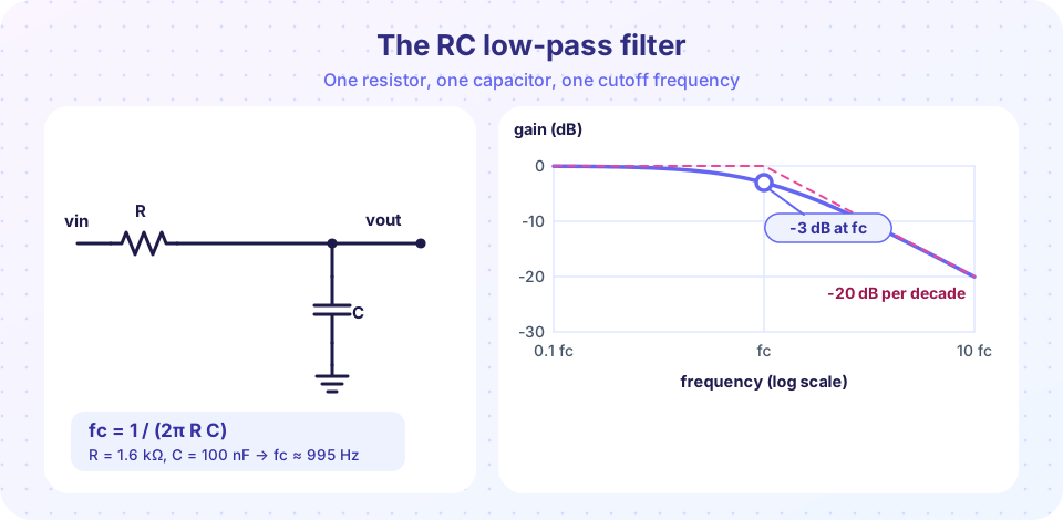
Put the resistor in series with the signal and the capacitor from the output to ground. The output is the voltage across the capacitor, from the divider rule:
H(f) = vout / vin = Xc / (R + Xc)   (with proper complex numbers)
|H(f)| = 1 / √(1 + (f / fc)²)
phase = -arctan(f / fc)
fc = 1 / (2π R C)
Read off the main points:
- Far below
fc:|H| ≈ 1(0 dB) and the phase is near 0°. - At
fc:|H| = 1/√2 = 0.707(-3 dB) and the phase is -45°. - Far above
fc:|H| ≈ fc / f, so every tenfold increase infcuts the gain tenfold: -20 dB per decade (about -6 dB per octave).
Worked example. R = 1.6 kΩ, C = 100 nF. fc = 1 / (2π × 1600 × 100×10⁻⁹) = 994.7 Hz. At f = 10 kHz, |H| = 1/√(1 + 10.05²) ≈ 0.099, so about -20 dB: a 10 kHz tone is reduced to one tenth.
Time-domain view
The same circuit smooths steps. A sudden jump in vin makes the capacitor charge as v(t) = V(1 - e^(-t/τ)). The time to go from 10% to 90% is 2.2 τ, and since τ = 1/(2π fc), this rise time is 0.35 / fc. This links the frequency and time views: a filter with a low cutoff makes slow edges.
The high-pass filter
Swap the two parts: the capacitor in series, the resistor to ground. Now low frequencies are blocked because the capacitor is nearly open, and high frequencies pass.
|H(f)| = (f / fc) / √(1 + (f / fc)²)
phase = +90° - arctan(f / fc)  (positive: the output leads)
fc = 1 / (2π R C)  (same formula)
At fc the gain is -3 dB and the phase is +45°. Below fc the gain rises at +20 dB per decade. The high-pass is what a coupling capacitor and the following resistance form: in chapter 5 each coupling capacitor created exactly this kind of corner.
Design recipe
- Pick the cutoff
fc. - Pick a convenient
C(for audio, 10 nF to 1 µF). - Compute
R = 1 / (2π fc C)and round to a standard value. - Check what the source and load do (below).
For a 5 kHz low-pass with C = 10 nF: R = 1 / (2π × 5000 × 10⁻⁸) = 3.18 kΩ, so use 3.3 kΩ (fc = 4.82 kHz).
Loading: the most common mistake
The formulas assume an ideal source and no load. Real life differs:
- A source with its own resistance
Rsadds toR: effectivelyfc = 1 / (2π (R + Rs) C). - A load
RLin parallel withCchanges the DC gain toRL / (R + RL)and shiftsfc. - Cascading passive stages makes them interact: the second RC loads the first, and the combined response is not the product of the two ideal ones. Separate stages with an op-amp buffer, which is exactly what active filters do in the next lesson.
A good rule: the load resistance should be at least ten times R.
Common misconceptions
"At the cutoff frequency the signal is blocked." It is reduced to 70.7% of its voltage (half the power), not blocked.
"Two identical RC stages make a 40 dB/decade filter with the same cutoff." The second stage loads the first and the -3 dB frequency drops to about 0.64 fc, so the combined filter is not as sharp as the ideal product suggests.
"A bigger capacitor always filters more." It lowers the cutoff frequency, so it filters out more of the high end, but a high-pass filter with a bigger capacitor lets more of the low end pass.
Try it
The first example is a Bode plot calculator for the low-pass and high-pass filters, in magnitude and phase. Edit R and C to explore other cutoffs.
Press Run (or Ctrl + Enter) to see the result here.
Program input · what you'd type while the program runs
Type the answers before you press Run, one per line. Each time the program reads a line (with input()), it gets the next line from this box.
The second example shows the time-domain side. A 200 Hz square wave passes through low-pass filters with different cutoffs; the edges become rounded exponentials. It is a numerical simulation of the ideal RC circuit with no load.
Press Run (or Ctrl + Enter) to see the result here.
Program input · what you'd type while the program runs
Type the answers before you press Run, one per line. Each time the program reads a line (with input()), it gets the next line from this box.
The third example is an interactive sine-wave tester: pick the filter type, the cutoff and the test frequency, and see the amplitude and phase change of the output wave.
Check your understanding
Quick check · 5 questions
of 5 answered You scored / 5 · perfect!
-
1. An RC low-pass uses R = 10 kΩ and C = 10 nF. What is fc?
fc = 1 / (2π × 10,000 × 10⁻⁸) = 1,592 Hz. -
2. What is the phase shift of an RC low-pass at its cutoff frequency?
At fc, arctan(1) = 45°, and a low-pass output lags the input. -
3. How much does a first-order low-pass attenuate a signal at 10 × fc?
|H| = 1/√(1 + 100) ≈ 0.1, which is -20 dB. -
4. Why should you buffer between two cascaded passive RC filters?
Interaction between passive stages shifts the cutoff and changes the shape; a buffer isolates them. -
5. A coupling capacitor of 1 µF feeds an amplifier whose input resistance is 10 kΩ. What is the high-pass cutoff?
fc = 1 / (2π × 10,000 × 10⁻⁶) = 15.9 Hz.
Summary
fc = 1 / (2π R C); the gain atfcis 0.707 (-3 dB) and the phase is ∓45°.- Low-pass: -20 dB per decade above
fc, phase 0° to -90°. High-pass: +20 dB per decade belowfc, phase +90° to 0°. - Time constant
τ = R C; rise time is about0.35 / fc. - Source and load resistances shift the cutoff; buffer cascaded stages.
Next: Active filters
Track your progress
Create a free account to tick off lessons and pick up where you left off on any device.
of Analog Electronics lessons completed