


















Lesson 11 of 46 · Bipolar Transistors
Chapter 3 overview: the bipolar transistor
Get the big picture of the bipolar junction transistor: how a small base current controls a large collector current, and how this chapter builds from regions to amplifiers.
In 1947, John Bardeen and Walter Brattain at Bell Laboratories made a device from germanium and two closely spaced metal points that could amplify a signal. It was the point-contact transistor. William Shockley, their group leader, then worked out the theory of a sturdier design built from layers of semiconductor, the junction transistor, which was demonstrated in 1951 and became the bipolar junction transistor (BJT) used for the next several decades. The three men shared the 1956 Nobel Prize in Physics. Before transistors, amplification needed vacuum tubes: large, hot, fragile and power hungry. The BJT replaced them in radios, computers and telephones, and it remains the best choice for many analog jobs today.
This chapter explains how a BJT works, how to use it as a switch, and how to model it for small signals. The next-but-one chapter adds the circuits that make it a stable amplifier.
What you will learn
- What a bipolar transistor is and what its three terminals do
- The central idea: a small base current controls a much larger collector current
- The map of this chapter's lessons
- Where BJTs are still the right choice
Key terms
BJT: bipolar junction transistor, a three-layer device (NPN or PNP) that amplifies current.
Base, collector, emitter: the three terminals. The small base current controls the large collector current.
β (beta): the current gain, I_C / I_B in the active region, typically 50 to 300.
NPN and PNP: the two polarities. This course uses NPN for examples; PNP works the same with all voltages and currents reversed.
Transconductance (g_m): the change in collector current per volt change on the base, I_C/V_T.
The central idea: a controlled current
A resistor's current is set by its voltage. A BJT's collector current is set by something else, the base. Put a small current into the base of an NPN transistor and a current about β times larger flows from collector to emitter, if the collector is positive enough. A typical small-signal transistor has β around 100, so 10 µA into the base allows about 1 mA at the collector.
This is what amplification means. A tiny change in the input produces a big change in the output. Put a resistor in the collector circuit and the changing current becomes a changing voltage that is much larger than the input voltage. The transistor is also a switch: with no base current, no collector current flows; with enough base current, the collector is pulled all the way down.
A more precise statement (developed in the next lessons) is that the base-emitter voltage sets the collector current exponentially, I_C = I_s e^(V_BE/V_T), exactly like a diode, and the base current is just the small price of a fraction (1/β) of that. The current-gain picture is easier for DC calculations; the voltage-controlled picture is easier for amplifiers. You will use both.
Where BJTs are used
- Audio and radio-frequency amplifiers with low noise and high gain per stage.
- Switches for LEDs, relays, buzzers and small motors, driven directly from a microcontroller.
- Current sources and mirrors inside analog chips, including the input and output stages of many op amps.
- Voltage regulators, power amplifiers and temperature sensors (using the −2 mV/°C drift of V_BE).
For high-speed digital logic and high-power switching, MOSFETs (chapter 4) usually win. For analog work with small signals, BJTs often give more gain per milliamp and better matching.
Chapter map
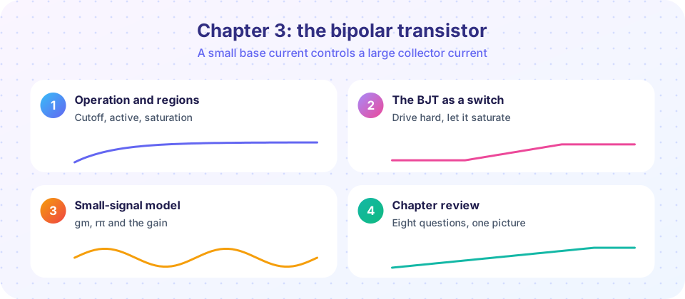
Three layers, two junctions
Three regions of operation
From DC to signals
Same device, three viewpoints.
- Operation and regions: the structure, the current equations, output curves and the load line.
- The BJT as a switch: designing base resistors and driving loads.
- The small-signal model: g_m, r_π and a first common-emitter amplifier.
- Chapter 3 review: one picture and ten questions.
Common misconceptions
"The transistor makes energy." It controls energy from the power supply. The extra output power comes from the supply, not from the transistor.
"The base current is the input and the collector current the output, so β is fixed." β varies between devices of the same type (often by a factor of 2 or 3), with collector current and with temperature. Good designs do not depend on it.
"A BJT is two diodes back to back." The two junctions are present, but the thin base is what gives gain. Two separate diodes would not amplify.
Try it
First, a quick table of the current gain at work: for a given base current, the collector current in the active region and the resulting power amplification.
Press Run (or Ctrl + Enter) to see the result here.
Program input · what you'd type while the program runs
Type the answers before you press Run, one per line. Each time the program reads a line (with input()), it gets the next line from this box.
Second, a water-valve picture as an interactive: the base is a small handle that controls a big flow. Move the slider to change the base current and watch the collector current and the output voltage across a collector resistor.
Check your understanding
Quick check · 4 questions
of 4 answered You scored / 4 · perfect!
-
1. In an NPN transistor, which terminal's small current controls the large current?
A small base current controls a much larger collector-to-emitter current. -
2. A transistor has β = 150 and a base current of 20 µA in the active region. What is the collector current?
I_C = β × I_B = 150 × 20 µA = 3 mA. -
3. Where does the extra power in the output of an amplifier come from?
The transistor only controls how much of the supply's power reaches the load. -
4. Which of these is not a typical BJT use?
Memory cells are made from MOSFETs today. BJTs shine in analog and small power-switching roles.
Summary
- A BJT has three terminals: base, collector and emitter; a small base current controls a large collector current.
- β (typically 50 to 300) relates them in the active region but varies widely between parts.
- The BJT is both an amplifier and a switch; the power comes from the supply.
- The chapter covers operation and regions, switching, the small-signal model and a review.
Next: Operation and regions
Track your progress
Create a free account to tick off lessons and pick up where you left off on any device.
of Analog Electronics lessons completed