


















Lesson 29 of 46 · Operational Amplifiers
Real op-amp limits: bandwidth, slew rate and offset
Understand why real op-amps run out of bandwidth, speed and accuracy: gain-bandwidth product, slew rate, input offset, bias current and output swing, with worked numbers.
The ideal op-amp from the last two lessons has infinite bandwidth and perfect accuracy. A real chip does not. Every datasheet is a list of ways the real part falls short, and a good designer knows which of those limits matter for a given circuit. In this lesson you will meet the five that cause the most trouble: gain-bandwidth, slew rate, input offset voltage, input bias current and output swing.
You do not need to memorize datasheet numbers. You need the habit of asking, at my signal frequency, amplitude and gain, which limit hits first?
What you will learn
- Use the gain-bandwidth product to predict closed-loop bandwidth.
- Compute the slew-rate limit and the full-power bandwidth.
- Estimate the output error caused by input offset voltage and bias current.
- Recognise limits on output swing and common-mode input range.
Key terms
Gain-bandwidth product (GBW): the product of closed-loop gain and closed-loop bandwidth; constant for a voltage-feedback op-amp over its roll-off region.
Unity-gain frequency (fT): the frequency where the open-loop gain falls to 1 (0 dB); for a single-pole op-amp it equals GBW.
Slew rate (SR): the maximum rate of change of the output voltage, in V/µs.
Input offset voltage (Vos): the small DC voltage that must be applied between the inputs to make the output zero.
Input bias current (Ib): the small current that flows into each input pin.
Gain-bandwidth product
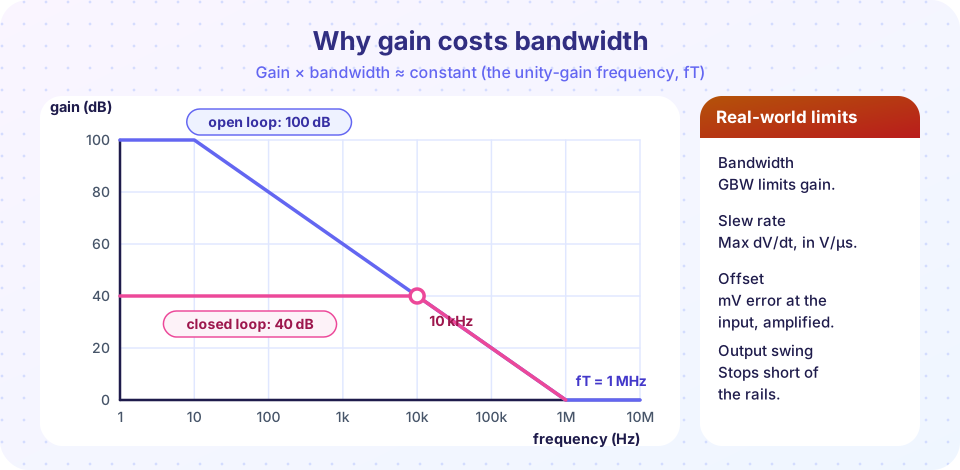
Inside the chip a small capacitor forces the open-loop gain to fall by 20 dB per decade above a low corner frequency (often around 10 Hz). The curve crosses 0 dB at the unity-gain frequency fT. In the picture above, fT = 1 MHz.
With feedback, the closed-loop gain G is flat until it meets the open-loop curve, and from there it follows that curve down. The meeting point, the closed-loop bandwidth, is
f_bandwidth ≈ GBW / G (noninverting gain G; for the inverting amplifier use the noise gain 1 + Rf/Rin)
Worked example. An op-amp has GBW = 1 MHz. At a gain of 11 the bandwidth is about 1 MHz / 11 = 91 kHz. At a gain of 100 it is 10 kHz, which is barely enough for audio. If you need a gain of 1000 across the audio band (20 kHz), you cannot get it from one such stage: you need two stages of about 32 each (each is 31 kHz wide, and the pair together is about 20 kHz), or an op-amp with a higher GBW.
Slew rate
GBW describes small signals. Large signals hit a different wall: the output cannot change faster than the slew rate. A sine wave v = Vp sin(2πft) has a maximum slope 2π f Vp. The output follows the sine only if
2π · f · Vp ≤ SR
The highest frequency at which the full output amplitude Vp is undistorted is the full-power bandwidth:
f_max = SR / (2π · Vp)
For a classic part with SR = 0.5 V/µs and a 10 V peak output, f_max = 0.5×10⁶ / (2π × 10) = 7.96 kHz. Above that, a sine wave turns into a triangle with a rate-limited slope, which sounds harsh in audio and is plainly wrong in a measurement. Fast op-amps reach hundreds of V/µs.
Notice that GBW and slew rate are independent limits. A small 100 mV signal at 100 kHz might be fine by slew rate (slope 2π × 10⁵ × 0.1 = 0.063 V/µs) but limited by GBW if the gain is high. A 10 V signal at 100 kHz might be fine by GBW at gain 1 and badly limited by slew rate.
Input offset voltage
A real op-amp behaves as though a small battery Vos sits in series with one input. A 741-class part has a typical Vos of 1 mV and up to 6 mV; precision parts get below 100 µV. The circuit amplifies this DC error by the noise gain, 1 + Rf/Rin, which equals the non-inverting gain:
Vout error = Vos · (1 + Rf / Rin)
With Vos = 2 mV and a gain-of-100 inverting stage (Rf/Rin = 100), the output offset is 2 mV × 101 = 202 mV. That is a lot if you wanted to measure millivolts. Solutions: choose a lower-offset part, add an offset-trim pot where the chip has trim pins, or AC-couple the signal.
Input bias current
The input transistors need a base (or leakage) current: bipolar op-amps draw tens of nanoamperes, JFET-input ones picoamperes. This current flowing through resistors creates additional offset. A classic fix is to make the resistance seen by both inputs equal; the bias currents then cause the same voltage drop at both, and the difference cancels. For the inverting amplifier, add a resistor Rin ∥ Rf from the + input to ground.
Output swing and common-mode range
The output cannot reach the supply rails. A general-purpose bipolar op-amp on ±15 V might swing to ±13 V; a rail-to-rail output stage gets within millivolts. The output also has a current limit, often about 20 mA, so low-ohm loads reduce the swing further. The input common-mode range is the span of input voltages where the chip works properly; for single-supply parts like the LM358 it includes ground, but for many dual-supply parts it ends 1 to 2 V before each rail.
Other numbers worth knowing
- Noise in nV/√Hz sets the minimum signal you can resolve.
- CMRR and PSRR (supply rejection) tell you how much common-mode or supply ripple leaks to the output.
- Stability: driving a big capacitor directly can make the op-amp oscillate; add a small series resistor.
Common misconceptions
"The op-amp has a bandwidth of 1 MHz, so my gain-of-100 amplifier works up to 1 MHz." It works up to about 10 kHz. Bandwidth shrinks as gain rises.
"Slew rate and bandwidth are the same limit." Slew rate limits large signals, bandwidth limits small ones. Check both.
"Offset is negligible, it is only millivolts." After a gain of 1000, 1 mV becomes 1 V.
Try it
The first example plots closed-loop frequency responses for three gains using a single-pole op-amp model with GBW = 1 MHz. It is a simple model of the small-signal behaviour; real chips have extra poles.
Press Run (or Ctrl + Enter) to see the result here.
Program input · what you'd type while the program runs
Type the answers before you press Run, one per line. Each time the program reads a line (with input()), it gets the next line from this box.
The second example shows slew-rate limiting in action. A 5 V peak sine wave passes through an op-amp model that can move at most 0.5 V/µs. The model is a rate limiter only; it ignores bandwidth effects.
Press Run (or Ctrl + Enter) to see the result here.
Program input · what you'd type while the program runs
Type the answers before you press Run, one per line. Each time the program reads a line (with input()), it gets the next line from this box.
The third example is a quick offset-error calculator. It multiplies the input offset voltage by the noise gain of an inverting stage and compares the result with the wanted signal. It is a first-order estimate.
Check your understanding
Quick check · 5 questions
of 5 answered You scored / 5 · perfect!
-
1. An op-amp has GBW = 3 MHz. About what bandwidth do you get at a closed-loop gain of 30?
Bandwidth ≈ GBW / G = 3 MHz / 30 = 100 kHz. -
2. What is the full-power bandwidth for a 10 V peak output and a slew rate of 1 V/µs?
f = SR / (2π Vp) = 1e6 / (2π × 10) ≈ 15.9 kHz. -
3. Vos = 1 mV and a non-inverting gain of 51. Roughly what DC offset appears at the output?
The offset is amplified by the noise gain: 1 mV × 51 = 51 mV. -
4. A small high-frequency signal is distorted even though its amplitude is tiny. Which limit is most likely at fault?
Small-signal rolloff is set by GBW; slew rate matters only for large, fast changes. -
5. How can you reduce the effect of input bias currents in an inverting amplifier?
Equal source resistance at both inputs makes the bias-current voltage drops cancel.
Summary
- Closed-loop bandwidth is about
GBW / gain; more gain means less bandwidth. - A signal must satisfy
2π f Vp ≤ SRto avoid slew-rate distortion. - Input offset is multiplied by the noise gain
1 + Rf/Rin; bias currents add more error. - Check output swing, common-mode range and stability with capacitive loads before choosing a part.
Next: Chapter review
Track your progress
Create a free account to tick off lessons and pick up where you left off on any device.
of Analog Electronics lessons completed