


















Lesson 15 of 46 · Bipolar Transistors
Chapter 3 review: Bipolar Transistors
Review how a BJT works, its regions, switch design and the hybrid-pi small-signal model with a summary picture, recap table and a ten-question practice quiz.
The bipolar transistor is a current-controlled current source with an exponential heart. In this chapter you saw it three ways. In the DC view, a small base current sets a collector current about β times larger. In the switch view, the transistor is either off or driven into saturation. In the small-signal view, it is a voltage-controlled current source with transconductance g_m = I_C/V_T. All three describe the same device, and choosing the right one is half the skill.
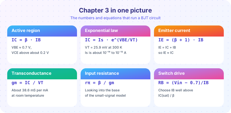
What you will learn
- Which transistor model fits which kind of problem
- How the formulas of the chapter connect
- Where you need more practice, from a ten-question quiz
Recap table
| Lesson | Key idea | Formula or rule | Watch out for |
|---|---|---|---|
| Operation and regions | Thin base gives current gain; three regions | I_C = βI_B, I_E = I_C + I_B, I_C = I_s·e^(V_BE/V_T) | β varies widely; check V_CE > 0.2 V for active |
| BJT as a switch | Saturate it with forced β ≈ 10 | R_B = (V_in − 0.7)/(I_C(sat)/10) | Flyback diode on inductive loads; storage time |
| Small-signal model | Linearize at the Q point | g_m = I_C/V_T, r_π = β/g_m, A_v = −g_m·R_C | DC first; keep v_be small |
One device, three questions
When you meet a transistor circuit, decide which question you are asking.
- "What are the DC voltages and currents?" Assume the active region (V_BE = 0.7 V, I_C = βI_B), calculate, and check that V_CE > 0.2 V. If not, it is saturated.
- "Is it a switch?" Make sure I_B is at least I_C(sat)/10. Add a flyback diode for coils.
- "What does it do to a small signal?" Use the DC current to find g_m, r_π and r_e. Draw the hybrid-π model. Then apply ordinary circuit analysis.
Notice the dependence: the small-signal values come from the DC solution. An error in bias propagates to every gain and resistance you calculate.
Common misconceptions
"β makes the design." A good design works for any β in the datasheet range. Switches use forced β, and amplifiers use feedback, so the answer does not depend on β.
"More collector current always means more gain." g_m rises with I_C, but r_π falls, the signal swing shrinks and the transistor dissipates more power. Choose the current for the job.
"The small-signal model is valid for any signal." It holds for signals that are small compared with V_T, a few millivolts at the base-emitter junction.
Try it
First, a table that ties the chapter together: for a range of bias currents it prints g_m, r_π, r_e, the unloaded gain of a stage with R_C = 4.7 kΩ, and the voltage left across the transistor.
Press Run (or Ctrl + Enter) to see the result here.
Program input · what you'd type while the program runs
Type the answers before you press Run, one per line. Each time the program reads a line (with input()), it gets the next line from this box.
Second, an interactive chart of the three regions. Slide the base current and the collector resistor and see which region the transistor sits in, based on the DC calculation from this chapter.
Check your understanding
Quick check · 10 questions
of 10 answered You scored / 10 · perfect!
-
1. A BJT has I_B = 30 µA and β = 150 in the active region. What is I_E?
I_C = 150 × 30 µA = 4.5 mA, I_E = I_C + I_B = 4.53 mA. -
2. In the active region V_BE is 0.7 V. By how much does V_BE change to increase I_C by a factor of 10?
ΔV = V_T·ln 10 = 59.5 mV. -
3. A transistor has V_CE = 0.15 V with a large base current. Which region is it in?
V_CE below about 0.2 V with both junctions forward biased means saturation. -
4. Design a switch: I_C(sat) = 20 mA from a 5 V input. Using a forced beta of 10, what is the base resistor?
I_B = 2 mA, so R_B = (5 − 0.7)/2 mA = 2.15 kΩ. -
5. What is g_m at I_C = 5 mA (V_T = 25.9 mV)?
g_m = 5 mA / 25.9 mV = 193 mS. -
6. With g_m = 193 mS and β = 100, what is r_π?
r_π = β/g_m = 100 / 0.193 = 518 Ω. -
7. A stage has g_m = 50 mS and R_C = 3 kΩ with no load. What is A_v?
A_v = −g_m·R_C = −0.05 × 3000 = −150. -
8. What does the −2 mV/°C temperature drift of V_BE imply for a fixed V_BE bias?
At constant V_BE a warmer transistor takes more current, which heats it further. -
9. Which circuit element protects a transistor driving a relay coil?
A flyback diode across the coil absorbs the voltage spike. -
10. Removing the emitter bypass capacitor from a CE stage with R_E = 1 kΩ and r_e = 20 Ω changes the gain from about −g_m·R_C to about:
R_E stays in the signal path, so the gain falls to roughly −R_C/(r_e + R_E).
Summary
- DC: I_C = βI_B in the active region, I_E = I_C + I_B, I_C = I_s·e^(V_BE/V_T); check V_CE > 0.2 V.
- Switch: drive with a forced β of about 10, add a base pull-down and a flyback diode for coils.
- Small signal: g_m = I_C/V_T, r_π = β/g_m, r_e ≈ 1/g_m; common-emitter gain = −g_m·R_C(effective).
- V_BE drifts −2 mV/°C and β varies widely: designs must not rely on either.
Next: Chapter 4: the MOSFET
Track your progress
Create a free account to tick off lessons and pick up where you left off on any device.
of Analog Electronics lessons completed