


















Lesson 36 of 46 · Power Supplies and Practical Design
Chapter 8 overview: power supplies and practical design
See how mains AC becomes clean DC: transformer, rectifier, filter capacitor and regulator, why each stage exists, and what practical design habits this chapter covers.
Every circuit in this track, from the transistor stages of chapter 5 to the oscillators of chapter 7, has been waiting on a quiet assumption: that somewhere there is a clean, steady DC voltage. Real life does not hand you one. The wall socket delivers alternating current at 120 V or 230 V, at 50 or 60 Hz, while your amplifier wants, say, a smooth 12 V. A power supply is the bridge between the two, and a poor one ruins an otherwise excellent design: hum in the speaker, jitter in a clock, readings that wander.
This chapter follows a signal-conditioning chain from the mains plug to the load. Each stage fixes exactly one imperfection of the stage before it, which makes the whole subject easy to reason about once you see the pattern.
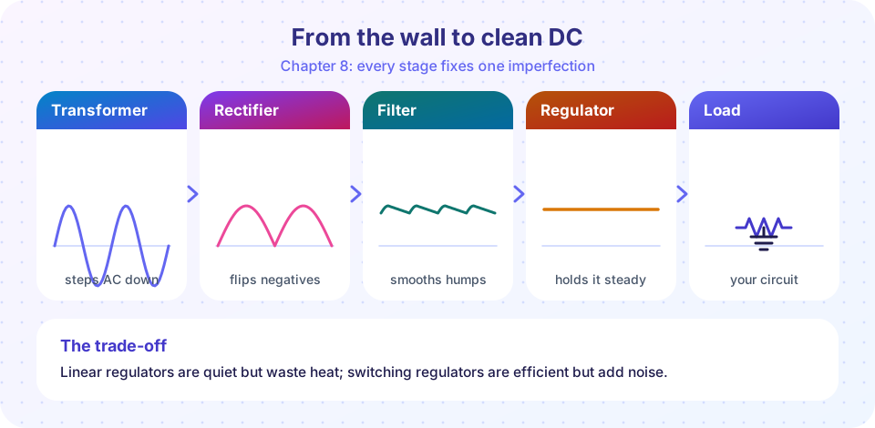
From the wall to your circuit
Four stages
Linear or switching?
Practical habits
What you will learn
- The purpose of each stage in a supply chain.
- Why linear and switching regulators coexist, and when to choose each.
- Which practical habits (decoupling, layout, protection) prevent most real-world problems.
The lessons in this chapter
| Lesson | What it covers |
|---|---|
| Rectifiers, ripple and the filter capacitor | Half-wave and bridge rectifiers, ripple formula, capacitor sizing, surge current |
| Linear regulators | Zener, 78xx and low-dropout regulators, dropout, heat, thermal design |
| Switching regulators and practical design | Buck converter, efficiency, decoupling, layout, protection |
| Chapter review | Recap and ten-question quiz |
Safety first. Mains voltage can kill. Do not build or open circuits connected to the wall socket unless you are trained. For practice, work from a certified plug-in transformer or a lab supply with a low-voltage output and a fuse. This course treats everything after the transformer, where the voltage is low and isolated.
The chain in words
- Transformer. Steps the mains voltage down (a 230 V mains source to, say, 9 V rms) and provides isolation, so the low-voltage side is not directly connected to the mains. The secondary is still AC.
- Rectifier. Diodes turn AC into pulsating DC. A bridge of four diodes uses both half-cycles, so the output has humps at twice the mains frequency (100 or 120 Hz).
- Filter capacitor. A large electrolytic capacitor charges at the peaks and supplies the load between them. What remains is a ripple, a small sawtooth on top of the DC.
- Regulator. A circuit that holds the output at a fixed value even when the input ripples, the mains voltage varies or the load changes.
The numbers shrink at every stage. A 9 V rms secondary peaks at 9 × 1.414 = 12.7 V. A bridge rectifier takes about 1.4 V (two diode drops) to leave roughly 11.3 V. With a good capacitor, the ripple might be 1 V. A 5 V regulator then removes almost all of it.
Linear versus switching
A linear regulator acts like an adjustable resistor in series with the load, burning off the voltage difference as heat. It is simple, cheap and quiet (low noise), but if you drop 12 V to 5 V at 1 A, you waste 7 W. A switching regulator instead chops the input on and off thousands of times per second and uses an inductor and capacitor to average the result. It can exceed 90% efficiency, but its switching edges generate noise that sensitive analog circuits dislike. Most designs use both: a switcher for the heavy lifting, followed by a small linear regulator for the quiet analog section.
Try it
The first example simulates the chain numerically: a 9 V rms transformer secondary, a bridge rectifier, a 2200 µF filter capacitor and an ideal 5 V regulator, with a 0.3 A load. The regulator is modelled as a perfect clamp, not a real chip.
Press Run (or Ctrl + Enter) to see the result here.
Program input · what you'd type while the program runs
Type the answers before you press Run, one per line. Each time the program reads a line (with input()), it gets the next line from this box.
The second example is a stage browser. Click a stage to see its output waveform; each is drawn from the same formulas as the simulation above.
Check your understanding
Quick check · 4 questions
of 4 answered You scored / 4 · perfect!
-
1. What is the main job of the filter capacitor?
The capacitor charges near the peaks and supplies the load between them, leaving a small ripple. -
2. A 12 V rms transformer secondary has a peak voltage of about:
Vpeak = Vrms × √2 = 12 × 1.414 = 17 V. -
3. A full-wave rectifier on 50 Hz mains produces humps at what frequency?
Both half-cycles become positive humps, doubling the frequency. -
4. Why do designers often follow a switching regulator with a small linear regulator?
The linear stage rejects the switching noise that would otherwise leak into the analog circuit.
Summary
- A supply chain turns mains AC into stable DC: transformer, rectifier, filter capacitor, regulator.
- Each stage fixes one imperfection; the numbers shrink (peak voltage, then diode drops, then ripple).
- Linear regulators are simple and quiet but waste power; switching regulators are efficient but noisy.
- Safety: only work on isolated, low-voltage supplies unless you are trained.
Track your progress
Create a free account to tick off lessons and pick up where you left off on any device.
of Analog Electronics lessons completed