


















Lesson 13 of 46 · Bipolar Transistors
The BJT as a switch: saturation, base resistors and loads
Design a transistor switch: choose the base resistor for saturation, drive LEDs and relays from logic pins, and protect against inductive spikes, with calculations.
A microcontroller pin can supply a few milliamps at 3.3 V or 5 V. A relay coil, a motor, a lamp or a string of LEDs may need ten or a hundred times as much current, and perhaps a higher voltage. A transistor bridges the gap: a few milliamps into the base turn a much larger load on or off. This is the most common use of a BJT in digital projects, and a good first design exercise because it needs only a few formulas and a careful eye on the worst case.
The key idea is saturation. You do not use the transistor as an amplifier here. You drive it hard enough that it is either clearly off or clearly fully on, and the details of β stop mattering.
What you will learn
- How cutoff and saturation make an on/off switch, and what V_CE(sat) means
- The design rule for the base resistor using a forced beta
- How to drive an LED or a relay from a logic pin
- How to protect against inductive spikes and check power dissipation
- Why switching off takes longer than switching on
Key terms
V_CE(sat): the collector-emitter voltage of a saturated transistor, typically 0.1 to 0.3 V.
Overdrive: supplying more base current than strictly needed so the transistor is firmly saturated.
Forced beta (β_forced): the ratio I_C(sat)/I_B actually used in saturation, deliberately well below the transistor's β.
Low-side switch: the transistor sits between the load and ground (as in the figure).
Pull-down resistor: a resistor from the base to ground that guarantees the transistor is off when the input floats.
Two states
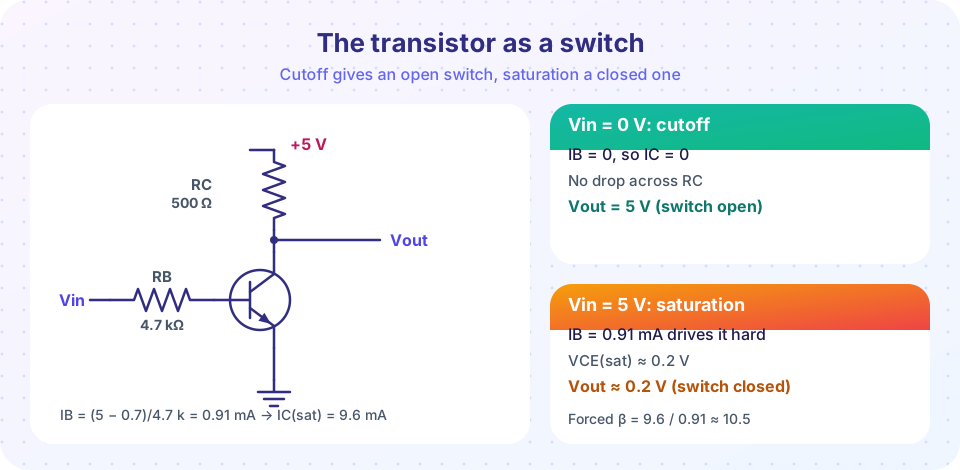
With the input at 0 V, the base-emitter junction gets no forward voltage, so I_B = 0 and I_C = 0. The load receives no current and the collector sits at the supply voltage: cutoff.
With a large enough input voltage, the base current becomes big enough to demand a collector current larger than the circuit can provide. The collector voltage falls until the base-collector junction also conducts; the transistor is in saturation with V_CE(sat) of about 0.2 V. The load current is then set by the supply and load alone:
IC(sat) = (VCC − VCE(sat)) / RL
In the figure, a 5 V supply and a 500 Ω load give I_C(sat) = (5 − 0.2)/500 = 9.6 mA. For the transistor to be saturated, I_B must exceed I_C(sat)/β. The input at 5 V through R_B = 4.7 kΩ gives I_B = (5 − 0.7)/4.7 kΩ = 0.91 mA, about nine times more than the 0.096 mA needed for β = 100. That safety factor makes the circuit work for any β from about 20 upward.
The design rule
- Find the load current. I_C(sat) = (V_CC − V_CE(sat) − any voltage across the load itself)/R.
- Choose a forced beta of about 10. I_B = I_C(sat)/10. This works even for weak transistors at high currents (where β falls). Use 20 for small signal currents under 10 mA if drive is scarce.
- Compute the base resistor. R_B = (V_in − V_BE)/I_B with V_BE ≈ 0.7 V (about 0.8 to 1 V at high currents).
- Round to a standard value, lower rather than higher, so the base current is a bit more than needed.
- Check the limits. Collector current below the rating (200 mA for a 2N3904, 800 mA for a 2N2222A, 1 A or more for power types), power dissipation, and the logic pin's current limit.
Example: a relay from a 5 V logic pin
A 12 V relay has a 400 Ω coil, so I_C(sat) = (12 − 0.2)/400 = 29.5 mA, within a 2N3904's 200 mA rating. A forced beta of 10 asks for I_B = 2.95 mA. From a 5 V pin, R_B = (5 − 0.7)/2.95 mA = 1.46 kΩ, so choose 1.2 kΩ (I_B = 3.6 mA, forced β = 8.2). A 10 kΩ pull-down from base to ground makes the relay stay off at power-up while the pin is still floating, and costs only 0.07 mA.
With a 3.3 V logic pin the same design needs R_B = (3.3 − 0.7)/2.95 mA = 880 Ω, so choose 820 Ω.
Example: an LED
For a red LED (2 V drop) at 10 mA from 5 V: R_C = (5 − 2 − 0.2)/10 mA = 280 Ω → 270 Ω, giving 10.4 mA. The LED sits in the collector circuit in place of the load; I_B = 1.04 mA for β_forced = 10, so R_B = (3.3 − 0.7)/1.04 mA = 2.5 kΩ → 2.2 kΩ.
Power dissipation
In the saturated state the transistor dissipates only P = I_C × V_CE(sat) = 29.5 mA × 0.2 V = 5.9 mW; in cutoff, essentially zero. Switches are efficient because they spend almost no time in the intermediate region where both current and voltage are large. Look at the transfer curve in the simulation below: the output only changes quickly in a narrow input window, and between those limits the transistor is acting as an amplifier and dissipating the most power. A slow input edge (a signal that rises gradually) can heat a transistor.
Inductive loads
A relay or motor is an inductor. When the transistor turns off, the coil current cannot stop at once, so the collector voltage spikes far above V_CC, which can exceed the transistor's V_CEO rating (40 V for a 2N3904) and destroy it. Put a flyback diode across the coil, cathode to the supply side, so the coil current has a loop to decay through (see Zeners and clipping circuits). The diode is a must for every relay, solenoid or motor driven by a transistor.
Switching speed
A transistor switches on in tens of nanoseconds, but switching off is slower. In saturation the base holds extra stored charge, and turning off requires removing it first. This storage time can be hundreds of nanoseconds up to a microsecond or more. More overdrive means deeper saturation and a longer storage time. For high speed, designers use less overdrive, Schottky clamps or a MOSFET instead. For relays and LEDs the effect is irrelevant.
Other arrangements
- High-side switching uses a PNP transistor between the supply and the load; the base is pulled low to turn it on.
- A Darlington pair (two transistors cascaded) gives a β of a thousand or more for very small drive currents, at the cost of a higher V_CE(sat) of about 1 V and slower turn-off.
- If you need a different logic voltage than the load voltage, the BJT's base is a convenient isolation point: the base needs only about 0.7 V to turn on, whatever the load voltage is.
Common misconceptions
"The base resistor is only to limit current into the base." It is, but the value matters: too large and the transistor does not saturate (it dissipates power and the output voltage is wrong); too small and you waste drive current.
"A transistor with β = 100 needs I_B = I_C/100." That is the minimum at the edge of saturation. Use I_C/10 for a reliable switch.
"The load can go anywhere in the circuit." In a low-side switch the load goes between the supply and the collector, not between emitter and ground (that would reduce the available base drive).
Try it
First, the transfer curve of the switch in the figure: output voltage against input voltage. See that the circuit is only a good switch outside the narrow transition window, and find the input level at which it becomes saturated.
Press Run (or Ctrl + Enter) to see the result here.
Program input · what you'd type while the program runs
Type the answers before you press Run, one per line. Each time the program reads a line (with input()), it gets the next line from this box.
Second, an interactive relay-driver calculator. Enter the coil resistance and logic voltage, and it computes the base resistor for a forced beta of 10 and shows the nearest standard value.
Check your understanding
Quick check · 5 questions
of 5 answered You scored / 5 · perfect!
-
1. A 12 V relay with a 300 Ω coil is switched by a saturated transistor with V_CE(sat) = 0.2 V. What is the coil current?
I_C = (12 − 0.2)/300 = 39.3 mA. -
2. Using a forced beta of 10, what base current is needed for 40 mA of collector current?
I_B = I_C/10 = 4 mA. -
3. A 3.3 V logic pin must supply 4 mA to the base. What base resistor value is closest?
R_B = (3.3 − 0.7)/4 mA = 650 Ω. In practice you would round down to a standard 560 or 620 Ω part. -
4. Why is a flyback diode needed across a relay coil?
The inductor keeps the current flowing; the diode gives it a safe loop. -
5. What is the main problem with leaving the transistor in the active region between on and off?
In the transition both V_CE and I_C are substantial, so the dissipation is highest.
Summary
- A BJT switch is either in cutoff (I_B = 0, open) or saturation (V_CE ≈ 0.2 V, closed).
- I_C(sat) = (V_CC − V_CE(sat))/R_L is set by the circuit; supply I_B = I_C(sat)/10 for reliable saturation.
- R_B = (V_in − 0.7 V)/I_B; add a base pull-down resistor of about 10 kΩ.
- A saturated switch dissipates only I_C × V_CE(sat); keep the transition fast.
- Always add a flyback diode across relays, solenoids and motors.
Next: The small-signal model
Track your progress
Create a free account to tick off lessons and pick up where you left off on any device.
of Analog Electronics lessons completed