


















Lesson 27 of 46 · Operational Amplifiers
The ideal op-amp and feedback
Learn the two golden rules of the ideal op-amp and use them to derive the gain of the inverting and non-inverting amplifiers, plus the voltage follower.
Analysing a circuit with a hundred-thousand-fold gain sounds hard, but two simple rules make op-amp circuits some of the easiest to solve in electronics. In this lesson you will see why those rules hold, use them to derive the gain of the two basic feedback amplifiers, and learn the traps that catch beginners.
Everything here assumes negative feedback: some of the output is connected back to the inverting (−) input. If the feedback goes to the non-inverting (+) input instead, the circuit behaves very differently, as you will see in the misconceptions section.
What you will learn
- State the two golden rules and explain why they hold with negative feedback.
- Derive the inverting gain
-Rf / Rinand non-inverting gain1 + Rf / Rg. - Design each amplifier from a required gain, including the voltage follower.
- Predict the input resistance of each circuit.
Key terms
Open-loop gain (A): the gain of the bare op-amp, vout = A · (v+ - v−).
Negative feedback: returning part of the output to the inverting input so that it opposes the input change.
Virtual earth (virtual ground): a node held at 0 V by feedback without being directly connected to ground.
Closed-loop gain: the gain of the whole circuit with the feedback network in place.
Voltage follower (buffer): a non-inverting amplifier with gain exactly 1.
The two golden rules
For an ideal op-amp with negative feedback:
- No current flows into either input. The input resistance is so high that the input currents are nanoamperes or less.
- The output adjusts until the two inputs are at the same voltage:
v+ = v−.
Rule 2 is not magic. The op-amp output is vout = A · (v+ - v−). With A = 100,000 and an output of 5 V, the difference v+ - v− is only 5 / 100000 = 50 µV. That is negligible next to volts, so the inputs are effectively equal. The feedback is what makes the output move to the one value that keeps this true: if v− falls below v+, the output rises, which raises v− back up.
The inverting amplifier
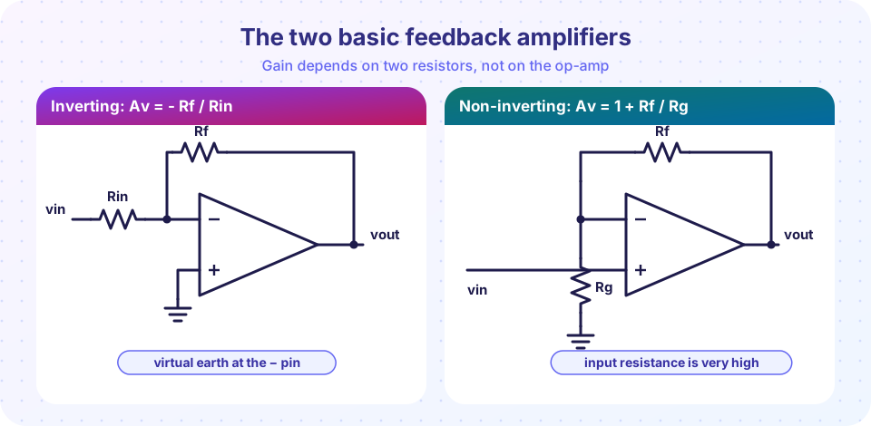
The input signal goes through Rin to the inverting input. A feedback resistor Rf connects the output back to that same input. The non-inverting input is grounded.
Because v+ = 0 V, rule 2 says v− = 0 V too: a virtual earth. Now apply Ohm's law:
- Current through
Rin:iin = (vin - 0) / Rin - By rule 1, none of that current enters the op-amp, so it all flows through
Rf:if = iin - The voltage across
Rfis0 - vout = if · Rf
Therefore vout = -vin · Rf / Rin, and
Av = -Rf / Rin
The input sees Rin connected to a virtual earth, so the input resistance is simply Rin, not very high. The gain can have any magnitude, even below 1.
Design example. You need a gain of -10 and want an input resistance of 10 kΩ. Choose Rin = 10 kΩ, so Rf = 100 kΩ.
The non-inverting amplifier
Now the signal goes straight to the + input. The output feeds a divider Rf and Rg, and the divider midpoint goes to the − input.
Rule 2 gives v− = v+ = vin. The divider gives v− = vout · Rg / (Rf + Rg). Equate and solve:
Av = vout / vin = 1 + Rf / Rg
The input is the high-impedance + pin, so the input resistance is very high. The gain is always at least 1 and is positive: the output has the same sign as the input.
Design example. You need a gain of 5 from a high-impedance sensor. Choose Rg = 1 kΩ, then Rf = 4 kΩ, because 1 + 4 / 1 = 5. In practice use 3.9 kΩ and 1 kΩ (gain 4.9) or a 4.02 kΩ 1% resistor.
The voltage follower
Make Rf = 0 and remove Rg altogether. The gain is 1 + 0 = 1. This buffer copies the input to the output but converts a weak, high-resistance source into a low-resistance one that can drive a load. It is the op-amp version of the emitter follower and is used all the time between a sensor and a later stage.
How accurate is "ideal"?
With a finite A, the exact non-inverting gain is
G = (1 + Rf/Rg) / (1 + (1 + Rf/Rg) / A)
For gain 11 and A = 100,000, G = 11 / (1 + 0.00011) = 10.9988, an error of about 0.011%. The error grows if the gain is large or A is small (it is also much smaller at high frequency, which the real-limits lesson covers).
Common misconceptions
"Virtual earth means the − pin is connected to ground." It is not. It sits at 0 V only because feedback forces it there; if you connect it to ground you destroy the gain.
"I can swap the + and − pins and nothing changes." Swapping turns the feedback positive. The output then slams into a supply rail (a comparator-like latch) instead of amplifying.
"The inverting amplifier has high input resistance." Its input resistance equals Rin. Use the non-inverting circuit or a buffer in front when the source cannot drive a few kilohms.
Try it
The first example solves the non-inverting amplifier with a finite op-amp gain using the exact DC formula. It confirms golden rule 2: the difference v+ - v− shrinks to microvolts. It is a numerical model of the DC behaviour.
Press Run (or Ctrl + Enter) to see the result here.
Program input · what you'd type while the program runs
Type the answers before you press Run, one per line. Each time the program reads a line (with input()), it gets the next line from this box.
The second example is an interactive inverting amplifier. It prints the currents and the voltage at the − pin so you can watch the virtual earth and rule 1 at work. It is a calculation based on the ideal rules.
Check your understanding
Quick check · 5 questions
of 5 answered You scored / 5 · perfect!
-
1. An inverting amplifier has Rin = 2.2 kΩ and Rf = 22 kΩ. What is its gain?
Av = -Rf / Rin = -22 / 2.2 = -10. -
2. A non-inverting amplifier has Rf = 9 kΩ and Rg = 1 kΩ. What is its gain?
Av = 1 + Rf / Rg = 1 + 9 = 10. -
3. What is the input resistance of the inverting amplifier?
The - pin is a virtual earth, so the source sees Rin connected to 0 V. -
4. Why can we say v+ = v- in a circuit with negative feedback?
vout = A (v+ - v-) with A large, so v+ - v- = vout / A is microvolts. -
5. What is the gain of a voltage follower?
With Rf = 0 and no Rg the formula 1 + Rf/Rg gives exactly 1. The follower copies the voltage and buffers the source.
Summary
- Golden rules: no input current; with negative feedback
v+ = v−. - Inverting amplifier:
Av = -Rf / Rin, input resistanceRin, virtual earth at the − pin. - Non-inverting amplifier:
Av = 1 + Rf / Rg, very high input resistance. - The follower is the non-inverting circuit with gain 1: a buffer.
Next: Op-amp circuits
Track your progress
Create a free account to tick off lessons and pick up where you left off on any device.
of Analog Electronics lessons completed