


















Lesson 31 of 46 · Filters and Oscillators
Chapter 7 overview: filters and oscillators
Preview chapter 7: how filters select frequencies, how active filters use op-amps, and how an amplifier with positive feedback becomes a sine-wave oscillator.
Real signals are mixtures. A microphone picks up your voice and the hum of the refrigerator. A radio antenna receives hundreds of stations at once. A sensor reading is wrapped in noise. To make sense of any of these you need circuits that choose frequencies: let the wanted ones through and block the others. That is a filter, and it is one of the most widely used analog circuits.
The same chapter also covers the reverse job. An oscillator produces a signal at one chosen frequency from nothing but a DC supply. Surprisingly, an oscillator is just an amplifier combined with a filter in a feedback loop, so the two topics belong together.
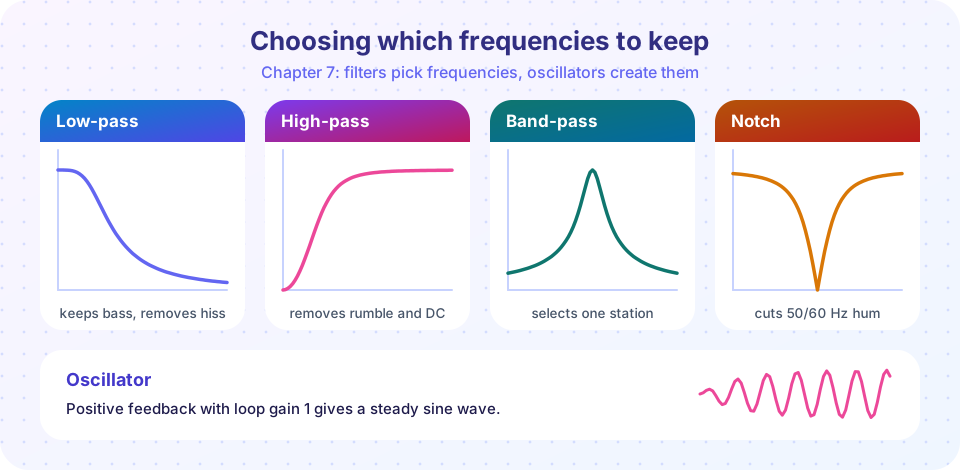
Four basic filters
Passive and active
Two numbers describe a filter
Oscillators
What you will learn
- What the four basic filter types do and how their responses look.
- How cutoff frequency, order and Q describe a filter.
- Why an oscillator is an amplifier with positive feedback.
The lessons in this chapter
| Lesson | What it covers |
|---|---|
| RC filters | First-order low-pass and high-pass, the -3 dB point, phase, Bode plots |
| Active filters | Sallen-Key second-order filters, Q, Butterworth and other responses |
| Oscillators | Barkhausen criteria, the Wien bridge, start-up and amplitude control |
| Chapter review | Recap and a ten-question quiz |
Frequency response
The central tool of this chapter is the frequency response: the gain of a circuit, usually in decibels, plotted against frequency on a logarithmic axis. The log axis is essential because audio spans three decades (20 Hz to 20 kHz) and radio spans many more. A straight-line slope on a log-log plot corresponds to a power law, so a filter that cuts 20 dB for every tenfold rise in frequency draws a straight sloping line, called a -20 dB per decade roll-off.
An ideal filter would have a "brick wall": everything below fc passes unchanged and everything above is blocked. No real circuit does this. Real filters have a gradual transition, and the sharper you make it, the more components, phase distortion and "ringing" you pay for. A first-order RC filter rolls off at 20 dB/decade, a second-order one at 40 dB/decade, and so on. Choosing the order is a trade between selectivity and complexity.
Why oscillators need a filter
An amplifier with positive feedback and exactly the right loop gain sustains a signal without any input. If the loop gain is a little too low the signal dies away; a little too high and it grows until the amplifier saturates. Only at a particular frequency does the feedback arrive in phase with the original. A filter in the feedback path picks that frequency. The result is a clean sine wave from a DC supply, the basis of every clock, tone generator and radio transmitter.
Try it
The first example plots the four basic response shapes together. The formulas are the standard normalised responses, not a particular circuit; x is the frequency divided by the centre or cutoff frequency.
Press Run (or Ctrl + Enter) to see the result here.
Program input · what you'd type while the program runs
Type the answers before you press Run, one per line. Each time the program reads a line (with input()), it gets the next line from this box.
The second example is a filtering playground. A 1 kHz tone is buried in 50 Hz hum and noise; choose a filter and cutoff and see how much cleaner the output becomes. It is a discrete-time model of a first-order RC filter.
Check your understanding
Quick check · 4 questions
of 4 answered You scored / 4 · perfect!
-
1. Which filter would you use to remove a constant 50 Hz hum from an audio signal?
A notch removes one narrow frequency while leaving the rest almost untouched. -
2. A second-order low-pass filter rolls off at:
Each pole adds 20 dB per decade, so two poles give 40 dB per decade. -
3. At the cutoff frequency of a low-pass filter, the gain relative to the passband is:
The cutoff frequency is defined as the point where the power is halved, -3 dB. -
4. An oscillator consists of:
The loop sustains a signal at the frequency where the feedback is in phase and the loop gain is 1.
Summary
- Filters select frequencies: low-pass, high-pass, band-pass and notch.
- A filter is described by its cutoff frequency, order and (for second-order) Q.
- Each pole adds 20 dB per decade of roll-off.
- An oscillator is an amplifier plus a frequency-selective feedback network with loop gain 1.
Next: RC filters
Track your progress
Create a free account to tick off lessons and pick up where you left off on any device.
of Analog Electronics lessons completed