


















Lesson 37 of 46 · Power Supplies and Practical Design
Rectifiers, ripple and the filter capacitor
Size a power-supply filter capacitor: half-wave, center-tap and bridge rectifiers, the ripple formula ΔV = I/(f·C), diode drops, surge current and capacitor ratings.
A rectifier by itself produces a lumpy output: a pulsating DC that falls to zero twice every mains cycle. Feeding that to an amplifier would put a loud 100 Hz buzz in the speaker. The standard cure is a big capacitor across the rectifier output. The capacitor charges up to the peak and then supplies the load while the humps are low. The size of the capacitor decides how much ripple is left, and sizing it correctly is the most common power-supply calculation you will perform.
In chapter 2 you studied rectifier diodes. Here we take the next step: how the capacitor and the rectifier interact, and how to predict the voltage you will actually get.
What you will learn
- Compare half-wave, center-tap and bridge rectifiers.
- Use
ΔV ≈ I / (fr · C)to size the filter capacitor. - Predict the DC output and the minimum voltage the regulator will see.
- Understand surge current and choose diode and capacitor ratings.
Key terms
Ripple (ΔV): the peak-to-peak variation of the DC voltage after filtering.
Ripple frequency (fr): the frequency of the humps: the mains frequency for half-wave, twice that for full-wave.
PIV (peak inverse voltage): the largest reverse voltage a diode must withstand.
Conduction angle: the fraction of each cycle during which the diodes conduct and recharge the capacitor.
Surge current (IFSM): the brief, large current a diode can survive, such as at switch-on.
Three rectifier layouts
- Half-wave (one diode): passes only positive half-cycles. Output humps at the mains frequency
f. Wasteful, with a large ripple. The transformer carries a DC component. - Full-wave with a center-tapped transformer (two diodes): each half of the secondary supplies one half-cycle. Humps at
2f. Each diode drops about 0.7 V; the reverse voltage across a non-conducting diode reaches twice the peak of one winding. - Bridge (four diodes): works with a single winding. Humps at
2f. Two diodes conduct at a time, so the loss is about 1.4 V (a bit more for large currents). PIV is only one peak voltage. The bridge is the default choice today.
With a bridge, the peak DC voltage before ripple is
Vpeak(DC) ≈ Vrms · √2 - 2 · 0.7 V
For a 9 V rms secondary that is 12.73 - 1.4 = 11.3 V.
The ripple formula
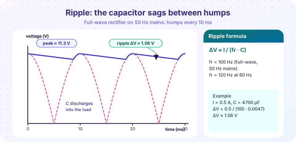
Between peaks the diodes are off, and the capacitor alone feeds the load current I. A constant current I removes charge at the rate I, so the voltage falls at dV/dt = I / C. The time between peaks is about 1 / fr, so the sag is
ΔV ≈ I / (fr · C)
This is an upper estimate, because the capacitor starts to recharge a little before the next peak, but it is close enough for design: about 10% high when the ripple is small, and more pessimistic when the ripple is large (the demo below shows both).
Worked example (the picture). A bridge on 50 Hz mains (fr = 100 Hz) supplies I = 0.5 A through C = 4700 µF:
ΔV = 0.5 / (100 × 0.0047) = 1.06 V
The average DC output is about Vpeak - ΔV/2 = 11.3 - 0.53 = 10.8 V, and the minimum is 11.3 - 1.06 = 10.3 V.
Sizing the other way. To keep the ripple below 0.5 V at 1 A on 60 Hz mains (fr = 120 Hz): C ≥ I / (fr · ΔV) = 1 / (120 × 0.5) = 16,700 µF. That is a huge capacitor, which shows why regulators, which tolerate large ripple, are worth the trouble: you can let the capacitor ripple by volts and clean it up afterwards.
What the regulator needs
The ripple's minimum matters, not the average. A 7805 needs at least about 7 V at its input (5 V plus a 2 V dropout), counted at the lowest point of the ripple and at low mains voltage (often -10%). Include that margin: take the mains at 90% of nominal when computing Vpeak.
Surge current
When the diodes conduct, they must refill the charge the load removed, but they only conduct for part of the cycle. The conduction time is only a fraction of the cycle, so the current pulses are much higher than the average load current. A 0.5 A load can produce diode pulses of 2-3 A or more, limited mainly by the transformer's winding resistance. Worse, at switch-on the empty capacitor is a short circuit and the diodes see the largest surge. Practical rules:
- Choose diodes with a forward current rating at least 2-3 times the load current and an
IFSMrating far above that. - Choose capacitor voltage rating ≥ 1.25 × Vpeak, because mains can be 10% high and electrolytic capacitors age.
- Observe polarity: an electrolytic installed backwards can vent or burst.
- Look at the capacitor's ripple-current rating and ESR; a cheap capacitor heats up under pulsed charging current.
Common misconceptions
"The DC voltage equals the rms value of the transformer." The capacitor charges to the peak, which is 1.41 times the rms value, less the diode drops.
"A bigger capacitor always helps without cost." It reduces ripple but increases the surge current and the stress on the diodes and the transformer.
"Ripple and noise are the same thing." Ripple is a low-frequency, predictable sawtooth at 100 or 120 Hz. Noise is broadband and random. A regulator removes ripple well but handles high-frequency switching noise less well.
Try it
The first example simulates the filter capacitor for a half-wave and a bridge rectifier and compares the measured ripple with I / (fr · C). It models ideal diodes with a fixed voltage drop and a constant-current load.
Press Run (or Ctrl + Enter) to see the result here.
Program input · what you'd type while the program runs
Type the answers before you press Run, one per line. Each time the program reads a line (with input()), it gets the next line from this box.
The second example looks at the diode current pulses. It simulates a bridge with a small transformer winding resistance and reports the peak current, the average current and the fraction of time the diodes conduct. It is a simplified model with a resistive source.
Press Run (or Ctrl + Enter) to see the result here.
Program input · what you'd type while the program runs
Type the answers before you press Run, one per line. Each time the program reads a line (with input()), it gets the next line from this box.
The third example is an interactive sizing tool. Pick the rectifier, capacitor and load; it reports ripple and the lowest voltage the regulator will see, with a warning if a 7805 would drop out.
Check your understanding
Quick check · 5 questions
of 5 answered You scored / 5 · perfect!
-
1. A bridge rectifier on 60 Hz mains feeds 2 A through 10,000 µF. What is the ripple?
fr = 120 Hz, so ΔV = 2 / (120 × 0.01) = 1.67 V. -
2. What is the peak DC voltage from a 15 V rms secondary through a bridge rectifier (before ripple)?
15 × 1.414 = 21.2 V, minus two diode drops (1.4 V) = 19.8 V. -
3. Why are diode current pulses larger than the load current?
The average diode current equals the load current but flows only during a small part of each cycle. -
4. How do you halve the ripple of a filter capacitor design?
ΔV = I / (fr C): doubling C halves the ripple. -
5. Which rating should the capacitor's working voltage exceed?
Allow for mains tolerance and ageing; a typical margin is 25% above the peak.
Summary
- A bridge rectifier gives a hump frequency of
2fand a peak ofVrms√2 - 1.4 V. - Ripple:
ΔV ≈ I / (fr · C); the minimum voltageVpeak - ΔV(at low mains) must stay above the regulator's need. - Diodes conduct in short high-current pulses; choose generous
IFSMand capacitor ratings. - Big capacitors cost surge current: let the regulator tolerate some ripple.
Next: Linear regulators
Track your progress
Create a free account to tick off lessons and pick up where you left off on any device.
of Analog Electronics lessons completed