


















Lesson 8 of 46 · Diodes and Rectifiers
Rectifier circuits: half-wave, full-wave and bridge
Build half-wave, full-wave and bridge rectifiers, calculate average output and peak inverse voltage, and size a smoothing capacitor for a given ripple.
The electricity from a wall socket alternates: it reverses direction 100 or 120 times a second (for 50 Hz or 60 Hz mains). Most electronics need steady direct current. The bridge between the two is the rectifier, a handful of diodes that only let current flow one way. Add a capacitor and the pulsing output becomes nearly flat. This is the first stage of nearly every power supply you will ever open.
This lesson builds the three common rectifiers, derives their average outputs, and shows how to choose the smoothing capacitor and diode ratings for a real design.
What you will learn
- How half-wave, center-tap full-wave and bridge rectifiers work
- How to compute the average (DC) output and the RMS value
- What peak inverse voltage (PIV) means and how to pick diodes
- How a smoothing capacitor works and how to estimate ripple
- Why real rectifiers conduct in short pulses
Key terms
Peak voltage (V_p): the maximum value of a waveform. For a sine, V_p = √2 × V_rms.
Average (DC) value: the mean of the waveform over a cycle, what a DC voltmeter reads.
PIV (peak inverse voltage): the largest reverse voltage a diode must block.
Ripple: the small periodic variation left on the DC output after smoothing.
Smoothing capacitor: a large capacitor across the load that holds the voltage between peaks.
Half-wave rectifier
The simplest rectifier is one diode in series with the load. During the positive half-cycle the diode conducts and the load sees the input minus the 0.7 V drop. During the negative half-cycle the diode blocks, so the output is zero.
For a sine of peak V_p, an ideal diode gives an average output of
Vdc = Vp / π ≈ 0.318 × Vp
The output has a pulse once per cycle, so the ripple frequency equals the mains frequency. The diode must block the full negative peak: PIV = V_p. Half-wave rectifiers waste half of the input waveform; they appear only in cheap, low-power circuits.
Full-wave rectifiers
A full-wave rectifier uses both halves of the input. There are two common arrangements.
Center-tap. A transformer with a center-tapped secondary and two diodes. Each diode takes one half of the winding. The output peak is V_p of half the winding (minus one diode drop), and each diode must block up to 2·V_p of that half-winding. It needs a special transformer but only drops one diode voltage.
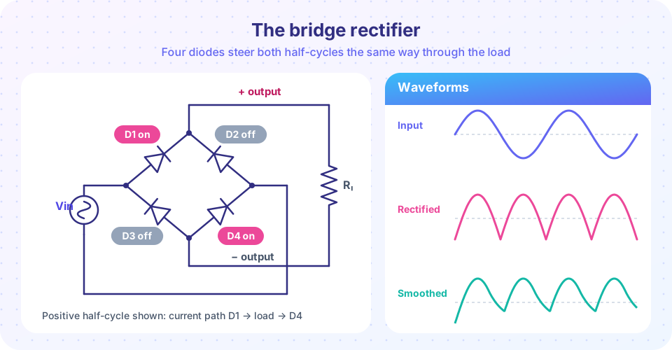
Bridge. Four diodes arranged as in the figure. During the positive half-cycle, D1 and D4 conduct; during the negative half-cycle, D2 and D3 do. Either way the current passes through the load in the same direction. Because two diodes are always in series, the output peak is
V_out(peak) = Vp − 2 × 0.7 V = Vp − 1.4 V
Each diode blocks only V_p, and no center tap is needed, so the bridge is the standard choice. Bridge rectifiers also come packaged as a single four-pin part.
For an ideal full-wave rectified sine, the average value doubles to
Vdc = 2·Vp / π ≈ 0.637 × Vp
and the ripple frequency is twice the mains frequency: 100 Hz in a 50 Hz country or 120 Hz in a 60 Hz one. Doubling the ripple frequency makes smoothing much easier.
| Rectifier | Diodes | Ripple frequency | Average (ideal) | Diode PIV |
|---|---|---|---|---|
| Half-wave | 1 | f | 0.318 V_p | V_p |
| Center-tap full-wave | 2 | 2f | 0.637 V_p | 2 V_p (of half-winding) |
| Bridge | 4 | 2f | 0.637 V_p | V_p |
Worked example: a 12 V supply
A transformer secondary gives 12 V RMS. The peak is V_p = 12 × √2 = 16.97 V. A bridge rectifier drops 1.4 V, so the unsmoothed peak output is 16.97 − 1.4 = 15.57 V. Diodes must block at least V_p = 17 V, so even a 1N4001 (50 V) would do, though the common 1N4007 is rated for 1000 V and costs the same.
Now add a smoothing capacitor. Between peaks the capacitor supplies the load current. If the load draws I and the capacitor discharges for nearly one ripple period (1/f_r), the voltage drop (the ripple) is approximately
ΔV ≈ I / (f_r × C)
For a 100 mA load and a 100 Hz ripple (50 Hz mains):
| C | Ripple ΔV (peak to peak) |
|---|---|
| 1000 µF | 1.0 V |
| 2200 µF | 0.45 V |
| 4700 µF | 0.21 V |
On 60 Hz mains the ripple is 120 Hz and each ripple value is about 17 % smaller. These are slightly pessimistic estimates (the capacitor recharges before a full period has passed) but close enough for design. The capacitor must be rated for more than the peak voltage: with 15.6 V peak, a 25 V electrolytic is the usual choice. Check the polarity: reversed electrolytic capacitors can fail violently.
Conduction in pulses
Once the capacitor is added, the diodes no longer conduct all the time. They turn on only near the top of each peak, when the input voltage exceeds the capacitor voltage, and they must recharge the capacitor in a short burst. The current pulses are several times larger than the average load current. That is why rectifier diodes are rated for repetitive peak current and surge current, and why transformers heat more than the average current suggests. Larger capacitors make the pulses even narrower and taller.
Common misconceptions
"The DC output equals the RMS voltage." A smoothed output approaches the peak, which is 1.41 times the RMS input (minus diode drops).
"A bigger capacitor is always better." It reduces ripple, but charging pulses grow larger and the inrush current at switch-on rises. The transformer and diodes need to handle them.
"A bridge rectifier output is pure DC." It is a rectified pulsing voltage until you smooth it; even after smoothing there is ripple.
Try it
First, a numerical simulation of a bridge rectifier with a smoothing capacitor and a resistive load. The program steps through time: when the rectified input minus the diode drops exceeds the capacitor voltage the diodes charge it, otherwise it decays through the load. Change C or the load and see how ripple responds. The simulation assumes ideal wiring (no transformer resistance), so charging pulses would be unrealistically sharp in a real supply.
Press Run (or Ctrl + Enter) to see the result here.
Program input · what you'd type while the program runs
Type the answers before you press Run, one per line. Each time the program reads a line (with input()), it gets the next line from this box.
Second, an interactive version of the same idea: slide the capacitor and the load current and watch the ripple. This is a simplified model (constant-current load).
Check your understanding
Quick check · 5 questions
of 5 answered You scored / 5 · perfect!
-
1. A sine wave has a peak of 10 V. What is the average output of an ideal half-wave rectifier?
V_dc = V_p/π = 10/3.14 = 3.18 V. -
2. A bridge rectifier is fed with a 20 V peak sine. What is the peak output with silicon diodes?
Two diodes conduct at a time: 20 − 1.4 = 18.6 V. -
3. Why is the ripple of a full-wave rectifier easier to smooth than a half-wave?
At twice the ripple frequency the capacitor discharges for half as long. -
4. A full-wave supply on 60 Hz mains has a 200 mA load and 4700 µF. What is the approximate ripple?
f_r = 120 Hz, so ΔV = 0.2 / (120 × 0.0047) = 0.355 V. -
5. Which statement about a smoothing capacitor is correct?
The diodes only conduct near the peaks to recharge the capacitor, so the current pulses are short and tall.
Summary
- Half-wave: one diode, V_dc ≈ V_p/π, ripple at the mains frequency, PIV = V_p.
- Full-wave (bridge): V_dc ≈ 2V_p/π, ripple at twice the mains frequency; the bridge drops two diode voltages.
- Smoothing ripple ≈ I/(f_r·C); size the capacitor for the load and the allowed ripple.
- Capacitor-input rectifiers draw current in short, tall pulses at the voltage peaks.
- Choose diodes for PIV, average current and surge current; rate the capacitor above the peak voltage.
Track your progress
Create a free account to tick off lessons and pick up where you left off on any device.
of Analog Electronics lessons completed