


















Lesson 30 of 46 · Operational Amplifiers
Chapter 6 review: operational amplifiers
Review the ideal op-amp rules, the inverting and non-inverting amplifiers, summers, integrators and real-world limits with a recap table, tools and a ten-question quiz.
Op-amps look intimidating at first, but this chapter reduced them to a handful of rules and a short list of limits. Before you move on to filters and oscillators, which are built from exactly these parts, take a moment to see the whole chapter at once.
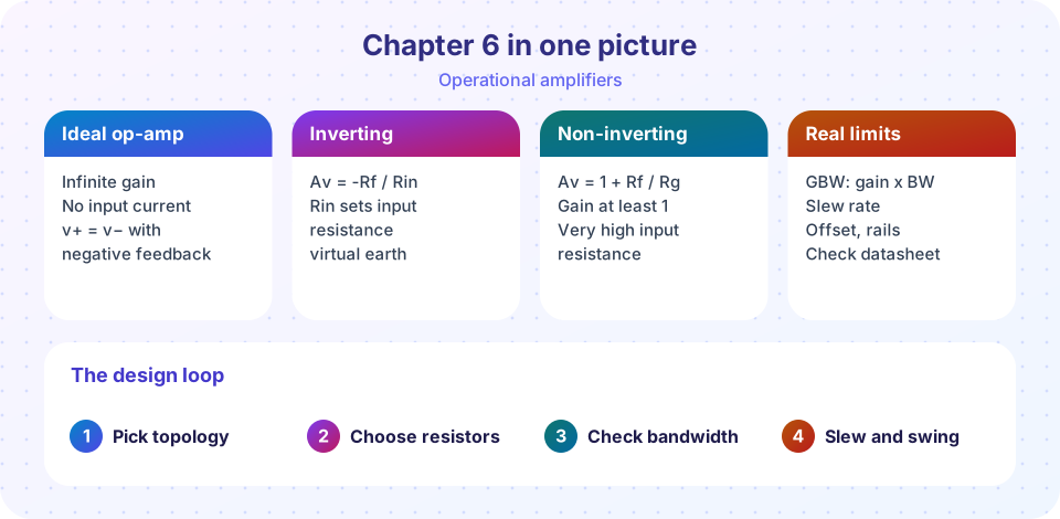
Recap table
| Topic | Key result | Lesson |
|---|---|---|
| Golden rules | No input current; v+ = v− with negative feedback |
Ideal op-amp |
| Inverting | Av = -Rf / Rin, Rin is the input resistance |
same |
| Non-inverting | Av = 1 + Rf / Rg, very high input resistance |
same |
| Follower | Gain 1, buffers a source | same |
| Summer | vout = -Rf Σ(vk / Rk) |
Op-amp circuits |
| Difference | (R2 / R1)(v2 - v1), matched ratios give CMRR |
same |
| Integrator | -(1/RC) ∫ vin dt |
same |
| Differentiator | -RC · dvin/dt |
same |
| Bandwidth | GBW / G |
Real limits |
| Slew limit | 2π f Vp ≤ SR |
same |
| Offset error | Vos · (1 + Rf / Rin) |
same |
A design checklist
When you design an op-amp circuit, work through these steps in order:
- Topology. Do you need inversion? Do you need a high input resistance? Inverting for flexibility, non-inverting for high-impedance sources.
- Resistors. Choose
RinorRgfirst (1 kΩ to 100 kΩ is typical), then calculateRfand round to the nearest standard value; recompute the real gain. - Bandwidth. Required bandwidth × gain must be well below the GBW.
- Slew rate. Check
2π f Vpagainst SR for your largest, fastest signal. - Swing and offset. Does the output peak fit inside the rails? Is the offset times the gain acceptable?
Try it
The first tool checks a few candidate chips against a design. The part profiles are rounded, illustrative typical values (the last one is a made-up fast precision part), so always read the real datasheet. It combines the three limits from the chapter into one verdict.
Press Run (or Ctrl + Enter) to see the result here.
Program input · what you'd type while the program runs
Type the answers before you press Run, one per line. Each time the program reads a line (with input()), it gets the next line from this box.
The second tool turns a gain target into resistor values from the standard E24 series and tells you the gain you really get. It is a calculator for the ideal formulas.
Check your understanding
Quick check · 10 questions
of 10 answered You scored / 10 · perfect!
-
1. Which statement is one of the two golden rules (with negative feedback)?
With negative feedback the output moves until v+ = v-. -
2. An inverting amplifier uses Rin = 4.7 kΩ and Rf = 47 kΩ. What is its gain and input resistance?
Av = -Rf / Rin = -10 and the input sees Rin = 4.7 kΩ. -
3. A non-inverting amplifier must have gain 21 with Rg = 1 kΩ. What is Rf?
1 + Rf / 1 kΩ = 21, so Rf = 20 kΩ. -
4. Which circuit would you use to convert a square wave into a triangle wave?
Integrating a constant gives a ramp, so a square wave becomes a triangle. -
5. GBW = 2 MHz. What bandwidth can a gain-of-50 stage achieve (approximately)?
2 MHz / 50 = 40 kHz. -
6. Output offset caused by Vos = 1.5 mV in a stage with noise gain 101 is about:
1.5 mV × 101 ≈ 152 mV. -
7. A 20 kHz, 8 V peak sine wave is slew-rate limited by a 0.5 V/µs op-amp. Why?
2π × 20000 × 8 = 1.005 × 10⁶ V/s = 1.0 V/µs, double the slew rate. -
8. Why does a summing amplifier let sources change independently?
Every input resistor drives a node held at 0 V, so currents add without voltages interacting. -
9. What happens if you swap the + and − pins of an inverting amplifier?
Positive feedback drives the output to a rail instead of regulating it. -
10. Which limit usually affects a tiny high-frequency signal in a high-gain stage first?
Small-signal bandwidth is set by GBW / gain.
Summary
- The ideal op-amp rules make circuits solvable with Ohm's law and Kirchhoff.
- Resistor ratios set gain; matching sets accuracy; capacitors turn the op-amp into an integrator or differentiator.
- Always check bandwidth, slew rate, offset, swing and stability in the real part.
- Filters and oscillators in the next chapter reuse these building blocks.
Track your progress
Create a free account to tick off lessons and pick up where you left off on any device.
of Analog Electronics lessons completed