


















Lesson 3 of 46 · Getting Started
Voltage dividers and Thévenin equivalents
Learn the voltage divider, why loading changes it, and how a Thévenin equivalent reduces any linear network to a source and a resistor, with simulations.
A voltage divider is two resistors that turn a big voltage into a smaller one. It is the most common circuit in electronics: it sets the bias of transistors, scales a sensor's voltage down for an analog-to-digital converter, and makes volume controls. It also teaches the most important lesson in analog design, that connecting something to a circuit changes the circuit. That "loading" effect leads directly to the Thévenin equivalent, a trick that replaces any complicated linear network, seen from two terminals, with one voltage source and one resistor.
If you understand this lesson, source and load, input and output resistance later become easy.
What you will learn
- The unloaded voltage divider formula and when it applies
- Why a load changes a divider's output, and how to compute the new value
- How to find a Thévenin equivalent: open-circuit voltage and resistance with sources off
- How to use the equivalent to find power and voltage for any load
- What maximum power transfer means, and why amplifiers rarely use it
Key terms
Voltage divider: two resistors in series across a source; the output is taken from their junction.
Loading: the change in a circuit's voltage caused by connecting a load to it.
Thévenin equivalent: a single voltage source V_th in series with a resistance R_th that behaves like the original network at its two terminals.
Open-circuit voltage: the voltage at the terminals with nothing connected.
Output resistance: the resistance looking back into the terminals, with independent sources turned off.
The unloaded divider
Put R₁ and R₂ in series across a source V_in. They carry the same current I = V_in / (R₁ + R₂). The voltage across R₂ is I·R₂, so
V_out = V_in × R2 / (R1 + R2)
With V_in = 12 V and R₁ = R₂ = 6 kΩ, the output is 12 × 6/12 = 6 V. If R₂ is twice R₁, two thirds of the input appears at the output. The output is the fraction R₂/(R₁+R₂) of the input, so scaling both resistors by the same factor leaves V_out unchanged. Only the ratio matters, but the absolute size matters for how much current the divider wastes and how easily a load disturbs it.
This formula is exact only if nothing is connected to the output (or if what you connect draws negligible current). It is a statement about an open-circuit output.
What a load does
Now connect a load R_L across R₂. R₂ and R_L are in parallel, and the divider formula uses that parallel combination in place of R₂:
R2' = R2 ∥ RL = R2·RL / (R2 + RL)
V_out = V_in × R2' / (R1 + R2')
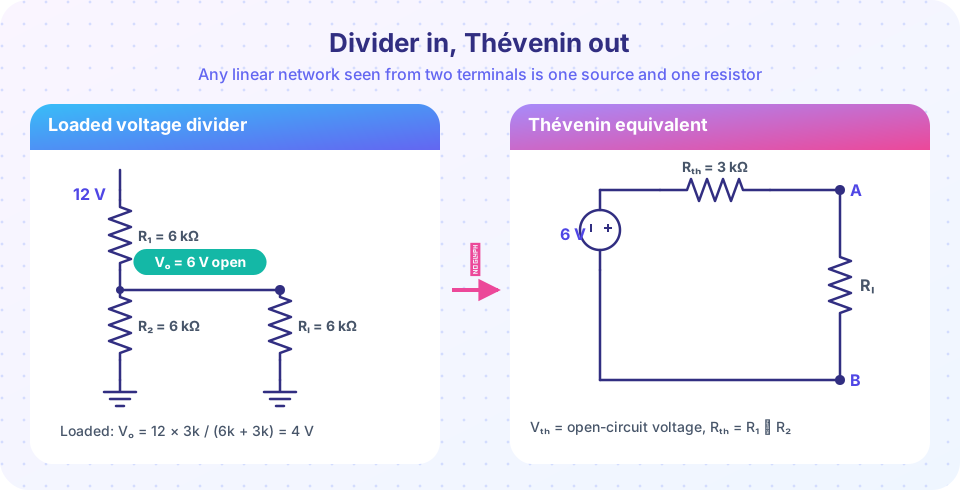
For our 12 V divider with a 6 kΩ load: R₂ ∥ R_L = 6 k ∥ 6 k = 3 kΩ, so V_out = 12 × 3/(6+3) = 4 V. The output fell from 6 V to 4 V, a 33 % error, just by connecting a load of the same size as the resistors. A good rule of thumb: the load should be at least ten times larger than R₂ if you want the output to change by less than about 10 %.
The lesson for design: a divider supplying a high-impedance load (such as the base of a MOSFET or an op-amp input) behaves as if unloaded. A divider supplying a low-impedance load needs low-valued resistors, at the cost of more wasted current.
The Thévenin equivalent
In 1883 Léon Thévenin showed (and Hermann von Helmholtz had earlier noted) that any linear network of sources and resistors, seen from a pair of terminals, is equivalent to a single voltage source V_th in series with a single resistance R_th. To find the pair:
- V_th is the open-circuit voltage: disconnect the load and calculate the voltage between the terminals.
- R_th is the resistance seen at the terminals with all independent voltage sources replaced by shorts (and current sources by opens).
For the divider: V_th = 12 × 6/12 = 6 V. With the 12 V source shorted, R₁ and R₂ are both between the output terminal and ground, so R_th = R₁ ∥ R₂ = 6 k ∥ 6 k = 3 kΩ. The equivalent circuit is a 6 V source behind 3 kΩ, exactly the right-hand half of the figure.
Now any load is trivial. For R_L = 6 kΩ: I = 6 V / (3 k + 6 k) = 0.667 mA and V_out = 0.667 mA × 6 k = 4 V. ✓ The same as before, but now you can swap loads in one line.
Why this matters later
Every amplifier stage has an output resistance, and every stage has an input resistance. When you connect stage 1 to stage 2, stage 1 is a Thévenin source (its open-circuit voltage gain and output resistance) feeding stage 2's input resistance, which is simply a divider. Much of amplifier design is making output resistances small and input resistances large, so those dividers lose little signal.
Maximum power transfer
How much power can the source deliver to the load? With V_th and R_th fixed, the load power is
P = V_th² · R_L / (R_th + R_L)²
This peaks at R_L = R_th, where P = V_th² / (4·R_th). For our example: 6² / (4 × 3000) = 3 mW. The load gets half of the power; the other half is lost in R_th, so the efficiency is only 50 %. Radio-frequency designers match impedances to move the most power. Audio and power designers do the opposite: they make the load much larger than the source resistance, so most of the voltage (and most of the power) reaches the load and the efficiency is high.
Common misconceptions
"The divider formula always works." It is valid only with no load, or a very high-resistance one.
"Thévenin's resistance is the resistance of the whole circuit." It is the resistance looking back into the terminals with sources turned off. It depends on which terminals you choose.
"Matching the load gives the best result." It gives the maximum power, not the best efficiency or the highest voltage.
Try it
The first demo is an interactive divider with a load. Drag the sliders to see how the loaded output departs from the ideal value, and how the Thévenin numbers change.
Second, a plot of how the loaded output and the power in the load depend on R_L for the example network. Find the maximum of the power curve and confirm it sits at R_L = R_th = 3 kΩ.
Press Run (or Ctrl + Enter) to see the result here.
Program input · what you'd type while the program runs
Type the answers before you press Run, one per line. Each time the program reads a line (with input()), it gets the next line from this box.
Check your understanding
Quick check · 5 questions
of 5 answered You scored / 5 · perfect!
-
1. A 10 kΩ and a 30 kΩ resistor form a divider across 20 V, with the 30 kΩ as R₂. What is the unloaded output?
V_out = 20 × 30/(10+30) = 15 V. -
2. A 100 kΩ load is connected across R₂ = 100 kΩ of an otherwise unloaded divider. What happens to the output?
The load is in parallel with R₂, lowering the lower resistance and so the output. -
3. How do you find a Thévenin resistance?
R_th is the resistance seen at the terminals with independent voltage sources replaced by shorts. -
4. A source has V_th = 10 V and R_th = 50 Ω. Which load gets the maximum power?
Maximum power transfer occurs when R_L = R_th = 50 Ω, giving 10²/(4×50) = 0.5 W. -
5. What is the efficiency at maximum power transfer?
The same current passes through R_th and R_L when they are equal, so half the power is lost in R_th.
Summary
- Unloaded divider: V_out = V_in·R₂/(R₁+R₂). A load in parallel with R₂ lowers the output.
- A load at least ten times R₂ disturbs the output by less than about 10 %.
- Thévenin: V_th is the open-circuit voltage; R_th is the resistance with sources off.
- Any load on a Thévenin source is a simple series circuit.
- Maximum power occurs at R_L = R_th, with only 50 % efficiency.
Next: The RC time constant
Track your progress
Create a free account to tick off lessons and pick up where you left off on any device.
of Analog Electronics lessons completed