


















Lesson 26 of 46 · Operational Amplifiers
Chapter 6 overview: operational amplifiers
Meet the op-amp: a high-gain building block that becomes precise with feedback. See the ideal rules, the circuits you will build, and the limits of real chips.
In chapter 5 you built an amplifier from a single transistor and fought with bias, β and temperature. The operational amplifier, or op-amp, packages that fight inside a small chip. It is a differential amplifier with enormous gain, typically 100,000 or more, a very high input resistance and a low output resistance. By itself that is almost useless, because the gain is too large and too unpredictable to use directly. The trick is negative feedback: connect part of the output back to the inverting input, and the large gain turns into a precise, stable, resistor-defined gain.
The name comes from analog computers of the 1940s, where such amplifiers, wired with resistors and capacitors, performed mathematical operations: adding, scaling, integrating. Integrated op-amps such as the Fairchild μA709 (designed by Bob Widlar) and the famous μA741 (Dave Fullagar, 1968) put the same idea on a chip that costs pennies today. Modern relatives like the LM358, TL072 and OPA2134 appear in nearly every audio, sensor and instrumentation circuit.
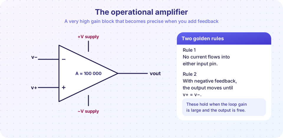
Five pins that matter
The golden rules
Circuits you will build
Where real chips differ
What you will learn
- Why an op-amp needs feedback and what the two golden rules mean.
- Which basic circuits you will analyse in this chapter.
- Which real-world limits you must check before choosing a chip.
The lessons in this chapter
| Lesson | What it covers |
|---|---|
| The ideal op-amp and feedback | Golden rules, inverting and non-inverting amplifiers, buffers, virtual earth |
| Op-amp circuits | Summing and difference amplifiers, integrator, differentiator, comparator warning |
| Real op-amp limits | Gain-bandwidth product, slew rate, offset, output swing, noise |
| Chapter review | One-page recap and ten-question quiz |
Ideal versus real
An ideal op-amp is a mathematical convenience with five properties: infinite open-loop gain, infinite input resistance, zero output resistance, infinite bandwidth and zero offset voltage. A real chip approximates these. A typical general-purpose part has a DC gain around 100 dB (100,000), an input resistance from megohms up to teraohms, an output resistance of tens of ohms, and a gain-bandwidth product of a few megahertz. Because the approximation is so good over the audio range, designers start with the ideal model and only check the limits at the end.
Why feedback is so powerful
Imagine the op-amp's gain is A = 100,000. In a non-inverting amplifier where a divider feeds back a fraction β = 1/11 of the output, the closed-loop gain is
G = A / (1 + A·β) ≈ 1 / β = 11
If A doubles or halves with temperature or from chip to chip, G barely moves, because A·β is much larger than 1. The precision of the result now comes from the resistors, which are cheap and accurate. This is the central bargain of feedback: trade excess gain for accuracy, linearity and predictable bandwidth.
Try it
The first example shows the bargain in numbers. It computes the closed-loop gain of a gain-of-11 amplifier for op-amp gains from 1,000 to 1,000,000 using the formula above. It models the DC gain only.
Press Run (or Ctrl + Enter) to see the result here.
Program input · what you'd type while the program runs
Type the answers before you press Run, one per line. Each time the program reads a line (with input()), it gets the next line from this box.
The second example is a small op-amp playground. Pick an amplifier type and resistor values, and see the output (a model of an ideal amplifier with a ±13 V output limit).
Check your understanding
Quick check · 3 questions
of 3 answered You scored / 3 · perfect!
-
1. Why is an op-amp used with negative feedback rather than open loop?
With feedback the closed-loop gain is approximately 1/β, set by resistor ratios rather than by the chip's variable open-loop gain. -
2. An amplifier has A = 100,000 and a feedback fraction β = 0.1. What is the closed-loop gain?
G = A / (1 + Aβ) = 100000 / 10001 ≈ 10, which is 1/β. -
3. Which pair describes an ideal op-amp?
An ideal op-amp has infinite open-loop gain, infinite input resistance and zero output resistance.
Summary
- An op-amp is a high-gain differential amplifier; negative feedback makes it precise.
- Closed-loop gain is about
1/β, set by resistors, not by the chip. - Ideal rules: no input current, and
v+ = v−when feedback is negative. - Real chips are limited by bandwidth, slew rate, offset and supply rails.
Track your progress
Create a free account to tick off lessons and pick up where you left off on any device.
of Analog Electronics lessons completed