


















Lesson 14 of 45 · Aircraft Structures and Propulsion
Airframe structures and loads
Learn the parts of an airframe, stress and strain, materials and specific strength, load factor and the V-n diagram, wing bending, cabin pressure stress and fatigue.
An aircraft structure has an odd job: it must be as strong as a bridge and as light as a feather. A bridge can afford to be heavy; an aircraft cannot, because every kilogram of structure is a kilogram less of payload or fuel. Aerospace structures engineers therefore work close to the limits of materials, and they rely on a few key ideas: stress, load factor, safety factors and fatigue. This lesson introduces them with numbers.
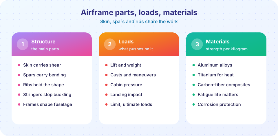
What you will learn
- The structural parts of a wing and fuselage and what each carries
- Stress, strain and the properties of aluminum, titanium and composites
- Load factor, limit and ultimate loads and how to read a V-n diagram
- How to estimate wing bending stress and pressurization stress
- What fatigue is and why airframes are inspected
Key terms
Stress (sigma) is force divided by the area it acts on, in pascals (N/m²).
Strain (epsilon) is the fractional change in length of a loaded material.
Load factor (n) is the ratio of the lift to the aircraft's weight, often quoted in g.
Limit load is the maximum load expected in service; ultimate load is the limit load times a safety factor of 1.5.
Fatigue is damage caused by repeated loading, even far below the yield stress.
The parts of an airframe
A modern aircraft is a thin-walled semi-monocoque structure: a skin stiffened by internal members.
- Skin carries shear and, on the fuselage, the pressure load.
- Spars run along the wing span. Their flanges (caps) carry the bending, and their webs carry the shear. A wing usually has a front and a rear spar, joined by skins to make a closed wing box, which also holds fuel.
- Ribs run along the chord. They hold the airfoil shape and spread loads between skin and spars.
- Stringers (or longerons) run along the span or fuselage. They stiffen the skin against buckling.
- Frames and bulkheads are the rings that hold the fuselage cross-section round.
Stress, strain and materials
When a bar of area A carries a force F, the stress is sigma = F / A. Strain is epsilon = delta_L / L. For small loads the material is elastic: sigma = E epsilon, where E is Young's modulus. Beyond the yield stress the deformation is permanent; at the ultimate stress the material fails.
Approximate properties, rounded:
| Material | Density (kg/m³) | Young's modulus E (GPa) | Yield stress (MPa) |
|---|---|---|---|
| Aluminum alloy 2024-T3 | 2,780 | 73 | about 345 |
| Aluminum alloy 7075-T6 | 2,810 | 72 | about 500 |
| Titanium Ti-6Al-4V | 4,430 | 114 | about 880 |
| Carbon fiber composite (unidirectional) | about 1,600 | about 135 along the fibers | not yielding; fails brittle |
Engineers compare materials by specific strength (strength divided by density). Composites and titanium win, which is why the Boeing 787 and Airbus A350 are about half composite by weight. Titanium is chosen near hot engines. Aluminum remains common because it is cheap, well understood and easy to repair.
Load factor and the V-n diagram
Level flight needs L = W, so n = 1. In a pull-up or a banked turn the wing makes more lift than the weight, and every part of the aircraft experiences extra load. In a level turn at bank angle phi, n = 1 / cos(phi): at 60 degrees the load factor is 2.
Certification rules set the load factors the aircraft must withstand. For large transport aircraft, the limit factor is +2.5 g to -1.0 g. The structure must carry the ultimate load, 1.5 times the limit, without failing, and the limit load without permanent deformation. For acrobatic aircraft the limit is much higher (+6 g or more).
The V-n diagram plots the load factor the aircraft can reach against airspeed. At low speed the wing stalls first: n = (1/2 rho V² S CL_max) / W, so the maximum load factor rises with V². At the maneuvering speed V_A = V_s sqrt(n_limit) the stall curve meets the structural limit, and above it the structure, not the wing, is the limit. Pilots slow to or below V_A in turbulence for this reason.
Wing bending: a first estimate
Lift acts along the span and the wing root must resist it as a bending moment. For an elliptical lift distribution, with load factor n, weight W and span b, the root bending moment (ignoring the wing's own weight relief) is
M = n W b / (3π)
For W = 686,466 N, b = 34 m, n = 2.5: M ≈ 6.19 × 10⁶ N·m. If the wing box is h = 0.8 m deep and the two spar caps carry the bending as a force couple, each cap must hold F = M / h, so with an ultimate factor of 1.5 and an allowable stress of 345 MPa, the cap area is
A = 1.5 M / (h sigma) = 1.5 × 6.19×10⁶ / (0.8 × 345×10⁶) ≈ 0.034 m²
That is only an estimate. It leaves out the skin, the wing's own weight, taper and many details, but it shows the scale of the numbers.
Pressurization
At 11 km the air pressure is about a fifth of that at sea level, so the cabin is pressurized to about the pressure at 2,400 m. The pressure difference, roughly 55 to 60 kPa (we use 58 kPa), pushes outward on the fuselage, and the skin carries a hoop stress
sigma = p r / t
For p = 58 kPa, r = 1.98 m and skin thickness t = 1.6 mm: sigma ≈ 72 MPa. That is low compared with the yield stress, but it cycles on and off every flight, which brings us to fatigue.
Fatigue
A metal that survives one load of 200 MPa may fail after a hundred thousand repetitions of 100 MPa. A tiny crack starts at a stress concentration (a rivet hole, a window corner), grows a little with each cycle and eventually breaks the part. This was the cause of the Comet disasters of 1954. The remedies are:
- Rounded window corners and smooth transitions, to cut stress concentrations.
- Safe-life or fail-safe design: parts have a fixed life, or multiple load paths so that one cracked part does not cause collapse.
- Inspection: scheduled checks find cracks before they become critical.
- Damage tolerance: the structure is designed so that cracks grow slowly enough to be found.
Try it
Press Run (or Ctrl + Enter) to see the result here.
Program input · what you'd type while the program runs
Type the answers before you press Run, one per line. Each time the program reads a line (with input()), it gets the next line from this box.
Press Run (or Ctrl + Enter) to see the console output here.
No output.
Common misconceptions
"Wings are fragile, because they flex." Airliner wings are designed to flex: the tips of a 787 can rise several meters in extreme tests. Flexibility spreads the load and is part of the design.
"If it passed the test, it is safe forever." Fatigue damage accumulates with every flight cycle, which is why airframes have inspection schedules and life limits.
"A higher safety factor is always better." Every extra bit of margin is weight. Aerospace uses 1.5 because other margins (conservative loads, material minimums, tests) are also in the chain.
Check your understanding
Quick check · 5 questions
of 5 answered You scored / 5 · perfect!
-
1. Which structural member mainly carries the wing's bending moment?
The caps (flanges) of the spars act like the top and bottom of an I-beam. -
2. A level turn at 60 degrees of bank gives a load factor of
n = 1 / cos(60 degrees) = 2. -
3. Ultimate load is
The ultimate factor of safety in aircraft structures is 1.5. -
4. Hoop stress in a pressurized cylindrical fuselage is
sigma = p r / t: bigger radius or pressure raises it, a thicker skin lowers it. -
5. Why are window corners rounded?
Sharp corners concentrate stress; the Comet crashes showed the consequence.
Summary
- A semi-monocoque airframe is skin, spars, ribs, stringers and frames, each with a role.
- Stress is
F/A; aluminum, titanium and composites trade density, stiffness and strength. - Load factor
n = L/W; transports are designed for +2.5 g to -1.0 g, with an ultimate factor of 1.5. - Root bending moment is about
n W b/(3π)for an elliptical load; hoop stress isp r / t. - Fatigue damages structures over cycles; design and inspection keep cracks under control.
Next: Aircraft propulsion
Track your progress
Create a free account to tick off lessons and pick up where you left off on any device.
of Aerospace Engineering lessons completed