


















Lesson 29 of 44 · Viscous Flow in Pipes
Minor losses and pipe systems
Add the losses from valves, bends, entrances and exits to pipe friction, use the energy equation with a pump, and solve a gravity-fed pipe system with code.
A real pipe system is not a long straight tube. It has an entrance from a tank, elbows, valves, reducers and an exit. Each fitting forces the flow to separate, swirl and mix, and each one wastes some energy. These are called minor losses, although in a short pipe with many fittings they can be larger than the friction itself.
This lesson shows how to count them, how to write the energy equation for a full system, and how to solve for the flow rate of a real pipeline.
What you will learn
- How to compute a minor loss with a loss coefficient
K. - How to write the energy equation between two points, including a pump.
- How to solve a gravity-fed system for the flow rate.
- How series and parallel pipes combine.
Key terms
Loss coefficient (K): a dimensionless number such that the head loss of a fitting is h_m = K V²/(2g).
Equivalent length (L_e): the length of straight pipe that causes the same loss as the fitting, L_e = K D / f.
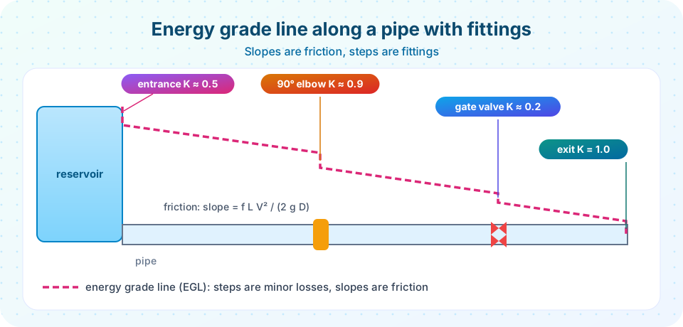
Energy grade line (EGL): a line plotted at height p/ρg + V²/2g + z, which falls along the pipe as energy is lost.
System curve: the head a system needs as a function of flow rate.
Minor losses
For a fitting, the head loss is written in terms of the local velocity head:
h_m = K V² / (2g)
Typical K values for turbulent flow (approximate, they vary with the exact design):
| Fitting | K |
|---|---|
| Sharp-edged entrance from a tank | 0.5 |
| Well-rounded entrance | 0.03 to 0.1 |
| Exit into a tank or the open air | 1.0 |
| 90° standard elbow (threaded) | 0.9 |
| 90° long-radius elbow (flanged) | 0.2 to 0.3 |
| Gate valve, fully open | 0.2 |
| Globe valve, fully open | 10 |
Sudden expansion A₁→A₂ |
(1 − A₁/A₂)² (based on the upstream V₁) |
The exit coefficient of 1.0 looks odd: where is the energy lost? The fluid leaves the pipe with kinetic energy V²/2g and mixes into the still reservoir, so that entire velocity head is dissipated. The sudden-expansion formula (Borda-Carnot) is one of the few K values derived theoretically; most others are measured.
To use K values, add all of them: Σ K. The total head loss in a pipe of constant diameter is
h_L = ( f L / D + Σ K ) V² / (2g)
You can also fold fittings into equivalent length: an elbow with K = 0.9 in a pipe with f = 0.02 and D = 0.1 m acts like 0.9 × 0.1 / 0.02 = 4.5 m of straight pipe.
The energy equation for a system
Between point 1 (upstream) and point 2 (downstream), with a pump adding head h_p:
p₁/ρg + V₁²/2g + z₁ + h_p = p₂/ρg + V₂²/2g + z₂ + h_L
Every term is a length (meters of fluid). Two common simplifications:
- If both points are free surfaces of large tanks open to the air, then
p₁ = p₂ = 0(gauge) andV₁ ≈ V₂ ≈ 0. The equation reduces toh_p = (z₂ − z₁) + h_L. - If no pump is present and the flow is driven by gravity, then
z₁ − z₂ = h_L.
Worked example: a gravity-fed pipe
Water flows from one tank to a lower tank through L = 200 m of commercial steel pipe, D = 100 mm (ε = 0.045 mm). The surface of the upper tank is H = 12 m above the lower one. The fittings are: sharp entrance (0.5), two standard elbows (2 × 0.9 = 1.8), a gate valve (0.2) and an exit (1.0), so Σ K = 3.5.
The energy equation gives H = (f L/D + Σ K) V²/(2g), so
V = √( 2 g H / (f L/D + Σ K) ).
f depends on V through Re, so iterate: guess f = 0.02, compute V, then Re and a better f, and repeat. After a few cycles V ≈ 2.43 m/s, Re ≈ 2.4 × 10⁵, f ≈ 0.0182, and the flow rate is Q = V π D²/4 ≈ 19 L/s. About 91 percent of the head is lost to friction in the pipe, since f L/D ≈ 36.5 compared with Σ K = 3.5.
Series and parallel pipes
- Series (one pipe after another): the same flow passes through each, and the head losses add:
h_L = h_{L1} + h_{L2} + …. - Parallel (pipes splitting and rejoining): the head loss across each branch is equal, and the flows add:
Q = Q₁ + Q₂ + ….
Parallel systems must be solved by choosing the common head loss and finding each branch flow, then adjusting until the flows sum to the total.
Common misconceptions
"Minor losses are always small." In a short pipe with many valves and bends they dominate. In the example above they are a minor share only because the pipe is long.
"The fitting loss depends on the fitting's size, not the speed." The loss grows with V², like friction does, which is why K is dimensionless.
"Bernoulli's equation works as written for pipe flow." The ideal Bernoulli equation has no loss term. The energy equation here adds h_L (and h_p for pumps).
Try it
First, solve the gravity-fed example by iteration. Change H, the diameter or the fittings and see how the flow rate responds.
Press Run (or Ctrl + Enter) to see the result here.
Program input · what you'd type while the program runs
Type the answers before you press Run, one per line. Each time the program reads a line (with input()), it gets the next line from this box.
Second, draw the system curve: the head a pump would need to push a flow Q through a pipe that lifts the water 10 m. It starts at the static lift and rises with Q² because losses grow with V². Compare three diameters.
Press Run (or Ctrl + Enter) to see the result here.
Program input · what you'd type while the program runs
Type the answers before you press Run, one per line. Each time the program reads a line (with input()), it gets the next line from this box.
Check your understanding
Quick check · 5 questions
of 5 answered You scored / 5 · perfect!
-
1. A fitting has K = 2.0 and the flow speed is 3 m/s. What is the head loss? (g = 9.81 m/s^2)
h_m = K V^2 / 2g = 2 x 9 / 19.62 = 0.917 m. -
2. Why does an exit into a tank have K = 1?
The fluid leaves with kinetic energy V^2/2g and that energy is dissipated in the tank. -
3. Two pipes in parallel: what is equal for both?
Both branches connect the same two points, so the head loss across each is the same and the flows add. -
4. Which term appears in the energy equation but not in the ideal Bernoulli equation?
Real systems dissipate energy, which is represented by h_L; pumps add head h_p. -
5. An elbow has K = 0.9 in a pipe with f = 0.03 and D = 0.15 m. What is its equivalent length?
L_e = K D / f = 0.9 x 0.15 / 0.03 = 4.5 m.
Summary
- Minor losses:
h_m = K V²/2g; add allKvalues and combine with friction as(f L/D + Σ K) V²/2g. - The energy equation between two points is
p/ρg + V²/2g + z + h_p = … + h_L. - Gravity-fed flow rate comes from iterating
V = √(2gH / (f L/D + ΣK)). - In series losses add; in parallel the head loss is shared and flows add.
- The system curve rises as
Q²from the static lift.
Next: Chapter 6 review
Track your progress
Create a free account to tick off lessons and pick up where you left off on any device.
of Fluid Mechanics lessons completed