


















Lesson 20 of 44 · Bernoulli and Energy
The Energy Equation and Grade Lines
Extend Bernoulli with pump head, turbine head and head loss to get the energy equation, compute pump power, and sketch the EGL and HGL for a pipe system.
Real pipe systems are not frictionless, and they contain pumps and turbines. Bernoulli's equation needs three extra terms before it can handle a city water main, a hydroelectric plant or a fuel line. The result, the energy equation, is the workhorse of pipe engineering. It also leads to two lines, the energy grade line and the hydraulic grade line, that engineers draw along a pipeline to see at a glance where energy is added, lost and stored as pressure.
What you will learn
- Write the energy equation with pump head, turbine head and head loss.
- Compute shaft power from head, flow rate and efficiency.
- Draw and read the energy grade line (EGL) and hydraulic grade line (HGL).
- Solve a reservoir-pipe problem where friction sets the flow.
Key terms
Head: energy per unit weight of fluid, in meters.
Pump head (h_p): energy added to the fluid by a pump, in meters of fluid.
Head loss (h_L): energy per unit weight converted to heat by friction and fittings.
Energy grade line (EGL): a plot of total head p/ρg + V²/2g + z along a flow.
Hydraulic grade line (HGL): a plot of p/ρg + z, the height a piezometer would show.
From Bernoulli to the energy equation
Apply the first law of thermodynamics to a control volume between sections 1 (inlet) and 2 (outlet) of a steady, incompressible flow. After dividing by ṁ g:
p₁/(ρg) + α₁V₁²/(2g) + z₁ + h_p = p₂/(ρg) + α₂V₂²/(2g) + z₂ + h_T + h_L
Each term is a head in meters. On the left: energy arriving at section 1 and added by a pump. On the right: energy leaving at section 2, taken out by a turbine, and lost to friction. Three notes:
αis the kinetic energy correction factor, because the true velocity is not uniform across a pipe.α = 1for uniform flow, about 1.05 for turbulent pipe flow (so people often use 1) and exactly 2 for laminar pipe flow.h_Lis always positive. Where it comes from (friction factors, minor losses) is chapter 6.- If there is no pump, turbine or loss, the equation reduces to Bernoulli with
H₁ = H₂.
Power
A pump delivering a flow Q with head h_p imparts a power to the fluid of P_fluid = ρ g Q h_p. The shaft power it requires is higher because the pump is not perfectly efficient:
P_shaft = ρ g Q h_p / η_pump
A turbine reverses the process: P_out = η_turbine ρ g Q h_T.
Worked example (pump). A pump lifts water at Q = 0.020 m³/s from a low reservoir to a tank 25 m higher through a pipe whose losses total 5 m. Both surfaces are at atmospheric pressure and the speeds there are zero.
- Energy equation from surface 1 to surface 2:
0 + 0 + 0 + h_p = 0 + 0 + 25 + 0 + 5, soh_p = 30 m. - Power to the fluid:
998 × 9.81 × 0.020 × 30 = 5874 W. - Shaft power at
η = 0.75:5874 / 0.75 = 7832 W ≈ 7.8 kW.
The pump supplies 30 m of head even though the tank is only 25 m higher: the extra 5 m is thrown away as friction.
Press Run (or Ctrl + Enter) to see the result here.
Program input · what you'd type while the program runs
Type the answers before you press Run, one per line. Each time the program reads a line (with input()), it gets the next line from this box.
Energy and hydraulic grade lines
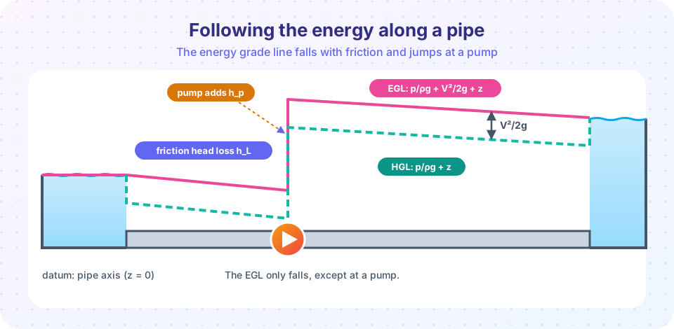
The EGL at each point is H = p/ρg + V²/2g + z measured above a datum. The HGL is p/ρg + z, exactly what a piezometer tube attached to the pipe would show. The EGL is always above the HGL by the velocity head V²/2g.
Rules for sketching:
- Free surface of a reservoir: both EGL and HGL sit at the surface (speed is zero).
- Friction: the EGL slopes downward in the flow direction (energy is lost). In a constant-diameter pipe the HGL has the same slope.
- Pump: the EGL and HGL both jump up by
h_p. Turbine: both drop byh_T. - Free jet exit to atmosphere: the HGL equals the elevation of the jet center (pressure is atmospheric).
- Change of diameter: the HGL jumps because
V²/2gchanges, but EGL does not (without loss). - HGL below the pipe: if the HGL dips below the pipe centerline, the gauge pressure there is negative (suction) and cavitation or air entry may occur. Move the pipe or raise the HGL.
Press Run (or Ctrl + Enter) to see the result here.
Program input · what you'd type while the program runs
Type the answers before you press Run, one per line. Each time the program reads a line (with input()), it gets the next line from this box.
The speed comes from the energy equation itself. For 100 m of 0.1 m pipe L/D = 1000 and f L/D = 20, so V²/2g = 30/(1 + 0.5 + 20) = 1.395 m and V = 5.23 m/s, Q = 41 L/s. Notice how friction uses up almost all of the head: 20 of the 21.5 velocity-head units. That is why long pipes need big diameters or pumps.
Common misconceptions
"Head loss means the water loses mass or flow." Flow is conserved. Only mechanical energy is lost, converted to heat (a tiny temperature rise).
"The EGL can rise along a pipe." Only where a pump adds energy. In a passive pipe it always falls.
"HGL is the energy line." The EGL is energy including velocity head; the HGL excludes it.
"The pump head is the elevation lift." It is the lift plus losses plus any velocity head you need at the outlet.
Check your understanding
Quick check · 5 questions
of 5 answered You scored / 5 · perfect!
-
1. A pump lifts 0.01 m³/s of water through 20 m with 2 m of losses. The pump head is
h_p = lift + losses = 20 + 2 = 22 m. -
2. With a pump efficiency of 70 %, the shaft power for ρ g Q h_p = 2.0 kW of fluid power is about
P_shaft = 2.0/0.70 ≈ 2.86 kW. -
3. The HGL is below the EGL by
EGL − HGL = V²/2g. -
4. At a pump the EGL
The pump adds energy per unit weight equal to h_p. -
5. Where the HGL falls below the pipe centerline, the gauge pressure is
HGL height above the pipe = p/ρg, so below the pipe means a negative gauge pressure.
Summary
- Energy equation:
p₁/ρg + α₁V₁²/2g + z₁ + h_p = p₂/ρg + α₂V₂²/2g + z₂ + h_T + h_L. - Pump shaft power:
ρ g Q h_p / η; turbine output:η ρ g Q h_T. - EGL = total head and only falls (except at pumps); HGL = EGL − V²/2g.
- Check that the HGL stays above the pipe, or suction and cavitation may result.
Next: Chapter 4 Review
Track your progress
Create a free account to tick off lessons and pick up where you left off on any device.
of Fluid Mechanics lessons completed