


















Lesson 38 of 47 · Internal Forces and Beams
Internal Forces and Beams: The Big Picture
How a beam carries load inside itself. Chapter 8 overview: axial force, shear, bending moment, sign conventions and shear and moment diagrams.
Everything we have done so far looked at forces from the outside: loads, reactions, pin forces. But a beam does not fail on the outside. A floor joist cracks somewhere in the middle, a diving board bends most near the fixed end, a steel shaft snaps at the section where it is weakest. To know whether a member is strong enough, you must know the forces inside it, at every section along its length.
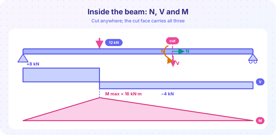
Imagine cutting a beam in two with a saw. Each piece is held in equilibrium by forces on the cut face. Those forces, which the other half exerts on this one, are the internal forces. They are the link between statics and strength of materials.
The big picture
At any cross-section of a plane beam there are three internal quantities:
| Quantity | Symbol | What it does |
|---|---|---|
| Axial (normal) force | N |
Stretches or squeezes the section along the beam axis |
| Shear force | V |
Tries to slide one side of the cut past the other |
| Bending moment | M |
Tries to rotate the faces; bends the beam |
The method to find them is the same as the method of sections for trusses: cut, draw a free body of one side, apply equilibrium. The new part is that the cut can be anywhere, so V and M become functions of position x. Plotting them gives the shear force diagram (SFD) and bending moment diagram (BMD), the two most important pictures in structural engineering.
Cut the beam
Three internal actions
Sign convention
Diagrams
Shortcuts
What each lesson covers
| Lesson | You will be able to |
|---|---|
| Internal forces in members | Cut a member anywhere and compute N, V and M with a consistent sign convention |
| Shear and moment diagrams | Build SFDs and BMDs by the equation method for point and uniform loads |
| Load, shear and moment relations | Draw diagrams in minutes with area rules, for cantilevers and overhangs too |
| Chapter review | Check all of it with a nine-question quiz |
A first look
A simply supported beam of span 6 m carries a single 12 kN load 2 m from the left support. The reactions are Ay = 8 kN and By = 4 kN. Cut the beam at x = 1 m: the left piece has Ay = 8 kN upward on its left end, so the cut face (the right face of this piece) must carry an 8 kN force acting downward to keep it in equilibrium. By the standard convention (right face down is positive) that is V = +8 kN, and the moment is M = 8 × 1 = 8 kN·m. Further along, the shear drops by the point load.
Press Run (or Ctrl + Enter) to see the result here.
Program input · what you'd type while the program runs
Type the answers before you press Run, one per line. Each time the program reads a line (with input()), it gets the next line from this box.
Press Run (or Ctrl + Enter) to see the result here.
Program input · what you'd type while the program runs
Type the answers before you press Run, one per line. Each time the program reads a line (with input()), it gets the next line from this box.
Check your understanding
Quick check · 3 questions
of 3 answered You scored / 3 · perfect!
-
1. How are the internal forces of a beam found?
An imaginary cut exposes the internal forces; equilibrium of either piece gives them. -
2. Which internal action tends to slide one face of a cut past the other?
Shear acts parallel to the cut face; it is the sliding force. -
3. In the standard convention, a sagging bending moment is:
Positive moment bends the beam concave up, compressing the top fibers.
Summary
- Internal forces at a section are
N,VandM; they come from a cut and equilibrium. - They vary along the beam; plot
V(x)andM(x). - The diagrams show where the beam is most heavily loaded and are the input to design.
Track your progress
Create a free account to tick off lessons and pick up where you left off on any device.
of Engineering Statics lessons completed