


















Lesson 41 of 47 · Internal Forces and Beams
Load, Shear and Moment Relations
Use dV/dx = -w and dM/dx = V to sketch shear and moment diagrams in minutes, for cantilevers and overhanging beams, with the area rules and a check that closes.
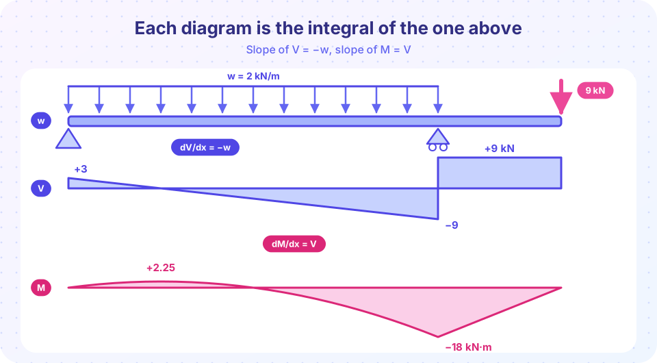
The equation method of the last lesson always works, but it is slow. Experienced engineers draw the diagrams by reading the loads: each diagram is the integral of the one above it. Once you see this, you can sketch an SFD and BMD in minutes, and you can spot errors at a glance.
The three diagrams (load, shear, moment) are linked by two simple differential relations, and every shortcut in this lesson follows from them.
What you will learn
- State and use
dV/dx = −wanddM/dx = V. - Apply the area rules between two points.
- Predict the shape (flat, line, parabola) of each diagram from the load.
- Draw diagrams for cantilevers and overhanging beams, and find inflection points.
Key terms
Load intensity w(x): downward distributed load per unit length (positive down).
Area rule: the change in V is minus the area under the load; the change in M is the area under the shear diagram.
Inflection point: where M changes sign.
Hogging: negative moment; the beam is concave down.
The relations
With w(x) positive downward, V and M in the standard convention, and x increasing to the right:
dV/dx = -w            dM/dx = V
V2 - V1 = -∫ w dx     (minus the area under the load diagram)
M2 - M1 = ∫ V dx      (the area under the shear diagram)
Derive the first by equilibrium of a tiny element of length dx: the shear on its right face is V + dV, the load pushes down by w dx, so V − (V + dV) − w dx = 0, giving dV = −w dx. Moments about the element's right face give dM = V dx.
At concentrated actions the relations become jumps:
| At a... | V |
M |
|---|---|---|
Downward point load P |
jumps down by P |
kink (slope changes) |
Upward reaction R |
jumps up by R |
kink |
Clockwise applied couple M0 |
no change | jumps up by M0 |
| Counterclockwise applied couple | no change | jumps down |
What the shapes tell you
| Load | Shear diagram | Moment diagram |
|---|---|---|
| None | horizontal line | straight sloped line |
Uniform w |
straight line sloping down | parabola (curved) |
| Triangular load | parabola | cubic curve |
The degree of the curve goes up by one each time you integrate. In practice remember this: under a downward uniform load the moment diagram is a hill (concave down when M is plotted upward), and where V = 0 the hill peaks.
Example 1: a cantilever with a uniform load
A cantilever of length L = 3 m is fixed at the left, free at the right, and carries w = 4 kN/m. Use x from the wall. At the free end, the shear and moment are both zero. Work from the wall using the reactions: V(0) = 12 kN (the wall pushes up with the total load) and M(0) = −wL²/2 = −18 kN·m.
V(x) = 12 - 4x       -> from +12 at the wall to 0 at the tip (straight line)
M(x) = -18 + 12x - 2x²  -> from -18 at the wall to 0 at the tip
Check with the area rule: the area under V from 0 to 3 is ½ × 3 × 12 = 18, and M rises from −18 to −18 + 18 = 0 ✓. The moment is negative everywhere: the beam is hogging, which is typical of cantilevers. Maximum shear and moment both occur at the support, which is why that is where cantilevers break.
Example 2: a beam with an overhang
A beam has a pin at A (x = 0), a roller at B (x = 6 m), and an overhang to C at x = 8 m. A uniform load w = 2 kN/m acts on AB, and a 9 kN point load acts at C. Moments about A: By × 6 = 12 × 3 + 9 × 8 = 108, so By = 18 kN and Ay = 21 − 18 = 3 kN.
Read the diagrams from left to right:
| Point | V |
M |
|---|---|---|
A, x = 0 |
+3 |
0 |
x = 1.5 |
0 (V decreases by 2 per meter) |
+3 × 1.5 / 2 = 2.25 (the area of the shear triangle) |
B−, x = 6 |
3 − 12 = −9 |
2.25 − ½ × 4.5 × 9 = −18 |
| B+ | −9 + 18 = +9 |
−18 (shear jumps, moment does not) |
C−, x = 8 |
+9 (no load between B and C) |
−18 + 9 × 2 = 0 |
| C | 9 − 9 = 0 |
0 |
The diagrams close: both end at zero, as they must at a free end. The largest moment is −18 kN·m over the support B, larger in size than the positive moment of 2.25 kN·m. Overhangs make beams hog over the support. The moment is zero at x = 3 m, an inflection point: for 0 < x < 3 the beam sags, then it hogs.
Common misconceptions
"The shear diagram must start and end at zero." It ends at zero at a free end or after the last reaction (a closed diagram), but it starts at the left reaction, which is generally not zero.
"A beam always sags." Overhangs and cantilevers hog. Reinforced concrete designers put the main steel at the top over supports for that reason.
"The moment is zero where the shear is zero." The moment has a local extremum where V = 0, not zero.
Try it
Press Run (or Ctrl + Enter) to see the result here.
Program input · what you'd type while the program runs
Type the answers before you press Run, one per line. Each time the program reads a line (with input()), it gets the next line from this box.
Press Run (or Ctrl + Enter) to see the result here.
Program input · what you'd type while the program runs
Type the answers before you press Run, one per line. Each time the program reads a line (with input()), it gets the next line from this box.
Check your understanding
Quick check · 6 questions
of 6 answered You scored / 6 · perfect!
-
1. dV/dx equals:
With w positive downward, the shear drops by the load: dV/dx = −w. -
2. Under a uniform downward load, the moment diagram is:
V is a sloped line, so integrating once more gives a parabola. -
3. Between two points the area under the shear diagram is +24 kN·m. The moment change is:
M2 − M1 = ∫ V dx, the area under the shear diagram. -
4. A cantilever of length 2 m carries a 15 kN load at its tip. The moment at the wall is:
M = −P L = −30 kN·m: the beam hogs. -
5. At a roller reaction, the shear diagram:
An upward force makes V jump up by its value, as seen when reading left to right. -
6. The moment is a maximum at the point where:
Since dM/dx = V, an extremum of M occurs at V = 0.
Summary
dV/dx = −w,dM/dx = V; each diagram is the integral of the one above.- Point loads jump
V; couples jumpM. - Read diagrams left to right; they must close at free ends.
- Overhangs and cantilevers hog; inflection points are where
M = 0.
Track your progress
Create a free account to tick off lessons and pick up where you left off on any device.
of Engineering Statics lessons completed